Introduction: How to Build Your Everything Really Really Fast
A few years ago, I wrote a short document on methods for rapidly fabricating elements of mechanical systems entitled How to Build Your Robot Really Really Fast. It was catered towards students in MIT’s 2.007 introductory design and manufacturing class for which I was a lab assistant at the time. The basic premise of the document was ways to build the structure and framework of a robot quickly using the tools available in the class, such as basic ‘garage’ tools like drill presses, saws, and sanders, as well as rapid prototyping and digital fabrication tools like abrasive waterjet cutters and laser cutters, weighing the tradeoffs of ‘build it now’ versus ‘design it now and have the machine make it later’. At the ti…
Introduction: How to Build Your Everything Really Really Fast
A few years ago, I wrote a short document on methods for rapidly fabricating elements of mechanical systems entitled How to Build Your Robot Really Really Fast. It was catered towards students in MIT’s 2.007 introductory design and manufacturing class for which I was a lab assistant at the time. The basic premise of the document was ways to build the structure and framework of a robot quickly using the tools available in the class, such as basic ‘garage’ tools like drill presses, saws, and sanders, as well as rapid prototyping and digital fabrication tools like abrasive waterjet cutters and laser cutters, weighing the tradeoffs of ‘build it now’ versus ‘design it now and have the machine make it later’. At the time, it was a compilation of my own experiences with those tools up to that point, and so its scope was fairly limited.
However, times have changed, and so have my experiences and views on the applicability of the methods presented in the document. New ones have been tried, and old ones have been refined. With access to the aforementioned digital fabrication processes by more makers and students proceeding at a ever-expanding pace, I decided it was perhaps time to rewrite the document in a fashion that made it more generally accessible to mechanical project builders.
And because I was sick of getting questions asking about why my t-nuts are no longer flat-bottomed. If the answer interests you, then keep reading!
Organization
The underlying message will be techniques used in design for assembly. Now, strictly speaking, I use the term it in a much different context than the manufacturing industry’s usage. But I believe the intents are the same: to design parts which are easy or quick to put together into the final product without complicated assembly steps. While for Sony it might have meant making all the parts of the Walkman insert and mate vertically, for hobbyists and "one-off" makers, this means trying to reduce the amount of hand-filing and fitting and drilling things in place, making "one way parts" which do not function if oriented incorrectly, etc. Common problems that many project builders run into.
So, this Instructable will be organized into several larger sections that address categories of challenges. For example, attaching parallel plates or making pinned joints. From there, there will be pages as necessary to demonstrate specific methods and parts usage techniques. I’ll try to include content that spans the spectrum of tool accessibility - from simple garage tools to a full RP facility including laser cutters and waterjet cutters. On each page, I’ll try to discuss a little about the recommended tools.
Periodically, in the sections, I’ll link to a resource that is useful on its own. For example, I’ll most likely link to Professor Alexander Slocum’s Fundamentals of Design many times - it really is a treatise on the principles underlying mechanical engineering, focusing on machine and mechanism design. It’s unproductive, then, for me to merely repeat his words. Other sides like roymech.co.uk are historical favorite go-tos for me, and will also be linked profusely.
The methods and examples presented will be primarily conceptual in nature, because they are generalizable to assemblies of different scales. I’ll include generous amounts of finite element simulations of structures and components in order to show the concept isolated by itself. As with all of my writings, math and formal analysis is only brought up when needed to cement a concept or is critical to preventing massive systemic failure. Your mechanical engineering and manufacturing professors will likely be disappointed.
Caveats
By no means is this going to be comprehensive overview of all design and assembly techniques. That’s practically impossible, and I believe also counterproductive. Part of the joy of engineering and building & making is the discovery of your own "style", the compilation of your own set of favorite techniques for approaching a problem. Inevitably, you will come up with a new custom solution to a problem. Hence, trying to list exhaustively how to mate thing A to thing B will artificially limit the search space of solutions, and make it very easy to ‘pick one, copy, and paste’ without understanding why a certain action is needed.
It is also not intended as a totally fresh introduction to mechanical engineering. That is, the question "what is a screw?" will not be answered. I am assuming that you have at least a passing familiarity with engineering terms like bolts, screw, axles, washers, nuts, and some knowledge of what machining processes do such as turning and milling. If you don’t, well, perhaps the substantial links and resources presented will change that!
All documents of this format will inevitably be clouded by the author’s style or flavor, and I make no pretensions to the contrary. The methods and parts used will be reflective of what I’ve done personally and what I’ve seen done by others in my local peer cloud, and the pictures and diagrams will probably be from my own past projects or those of my peers. It’s not my intention to make sure all of these become widespread, but more information and knowledge transfer is preferable, in my opinion, to less.
It’s important to note that practicians of classic 3D subtractive machining will probably not gain much from this Instructable. In my opinion, 3D machining (e.g. milling, turning, manual or CNC) is an entire means of building on its own, since it has very high equipment capital costs and associated learning curves. 2D production techniques are still substantially easier for people to gain access to, or hire out for lesser cost than having a machine shop. So, this will not be a "how to machine" guide.
Step 1: General Lessons and Themes
Before I begin the laundry list, there are some high-level points I want to make. These are issues to keep in mind as you adapt the concepts to your own design.
Right angles and in-plane angles are really easy.
If your project is free of design constraints enough that the outer appearance does not play significantly into functionality, then you’ll benefit more than if it needs to be pretty and sellable. Most of these methods are really good attaching square things to other square things. It’s relatively easy to check for straightness and squareness; not so easy for making sure two parts are mating at a specific angle.
There’s also a difference between in-plane angles and compound, that is out of plane and rotated, angles. Because much of this document is founded on planar structures and mechanisms (think anything you can do without lifting your hand off the table), there will be significantly more content on making those types of joints.
3D angles involve at least one frame member or structural element which has an acute angle or bevel angle cut into it. With generally 2D fabrication methods, this is much harder to achieve. There are ways of getting around this, such as approximating a 3D angle using 2D layers, but broadly speaking if there are compound angles in your design, custom legwork and 3D machining might be the only practical solution.
Speaking of constraints...
Constraining things properly is hard, but essential.
What I mean in this case is physical, mechanical constraints. All physical objects (that exist in 3 dimensions, anyway) have 6 degrees of freedom, and the goal of making a successful structure or mechanism is to eliminate all of the ones we don’t want. This involves the use of pin joints, planar/face mates, and fasteners strategically such that nothing is just flopping around unsupported.
A related concept is the "structural loop", which concentrates specifically on those floppy unsupported parts. It’s the path through which forces are reacted against in the device. Essentially, if your device was made of a very poorly cooked, rubbery Jello, what would move the most? And can you add elements that don’t interfere with the function of the design to make it less movable?
Hopefully by the end of reading through this document you will have a better understanding of how critical constraining parts in directions which optimally load the material is to creating a device which isn’t misaligned and floppy. If I can’t beat it into you, then surely Fundamentals can.
No Mostly-Tightened Nuts!
One hallmark of a "newbie" build is the amount of screws that have to be tightened a very specific amount, or nuts and bolts that have to be left very slightly loose. Any deviation results in a floppy arm or slanted wheel, or just total lockup of the mechanism in question. This means your device is always teetering on the edge of being too bent and wubby to function - any unexpected loads will probably cause total disappointment.
Bolts and screws work, fundamentally, by creating compression forces between the parts they are holding together. The compression forces, commonly called preload, determine to a degree how stiff the joint is because immense friction is created at the part interface thanks to those compression forces. The basic idea is that the preload force must be overcome before the structure will even begin thinking of maybe shifting, just a tiny bit. Hence, properly designed machine structures are predictably stiff in their operating regimes. And, if your parts are otherwise constrained, or even overconstrained, excursions outside of its design load can even be tolerated without failure.
My mission is to deter you from creating such abominations by hammering it in from the beginning that all your fasteners have to be tight. A large part of this document will be dedicated specifically to how to constrain rotating members and pin joints as a result.
Step 2: Magical Finger Joints: Joining Plates at Right Angles
You might have noticed that pretty much everything shown at the beginning had little slots and tabs in it. This has become a popular method of making 3D structures from 2D plates, spurred on by the digital fab movement starting some time in the 2000s. The name for the joint style is called "finger joint" after the woodworking technique from which it was derived.
These joints are advantageous to make because they positively locate features, to within the tolerances of the material and process, anyway. This is because the tabs must necessarily align and fit into the slots.
Additionally, they create structures which react to loads through the material. Finger jointed structures tend to rely on fasteners only to hold the structure together from expanding outwards *i.e. *unseating the finger joints. Otherwise, loads are directly transmitted through the fingers.
Prudent design is still necessary to ensure that the fingered edges are not loaded along the thickness axis, in which they are weakest, i.e. flapping using the finger joint as a hinge. A finite element analysis simulation is shown in image 6 - notice how significant stress builds up in the finger joints when the plates are bent. This will be discussed along with methods of preventing it.
Open (Underconstrained) Finger Joints
The simplest method of joining perpendicular plates with finger joints. This isn’t so much a joint as an alignment feature, without anything else (e.g. fasteners or welding) to keep the joint together. The joint is only strong in the direction of the edge, where the fingers are loaded in compression. This type of joint, especially with no backup, is vulnerable to bending Think opening up a stiff book.
Closed (Fully Constrained) Finger Joints
These joints have one part with fingers and the other with fully closed slots. More strictly, it can be interpreted as a type of mortise joint. The fully enveloping slot captures the fingered piece well in all 6 degrees of freedom, if fastened with screws, but suffers from the same "edge hinging" bending vulnerability without additional support.
These are more difficult to make correctly because material thickness tolerances can impact whether or not the slots fit significantly. This is discussed in more detail in Step 5, tolerancing.
Regular Patterns
There exist two popular ‘schools of thought’ when it comes to how many finger joints to use. One of them is what I term ‘sparse’ finger joints, in which a single joint consists of two slots and one fastening hole. That pattern itself is patterned several times, usually at least three - one on each end of the material, and one to hold down the center.
The other is what I call "edge stitching" in which the entire edge has a regular zig-zag pattern of fingers and mating slots. The distance between the ‘peaks and valleys’ is constant, and repeated for as long as possible. However, unless the part dimensions are a multiple of the slot width, there may be irregularities at the ends.
For example, 0.5" wide slots and tabs work well with a 2.5" (or, really any x.5") part width. If the part were instead wider, then the outermost two slots and mating tabs get increasingly wider. The same principle works in metric part lengths. For 12mm slots to be patterned regularly, the parts must be an odd number times 12mm. The extra lengths generally aren’t design problems, but for aesthetics, such as a "closing the box" design, it may be important. More on this subject is found in Step 6, making boxes.
Direct Welding
Notice that there’s been no discussion so far on how to join the actual edges. Later on, I’ll introduce methods of attaching the plates to each other with fasteners, but I do want to discuss welding.
While these joints have historically been the domain of plastics and wood, there are now an increasing number of project which use finger joints as alignment features in steel or aluminum with the intent of welding the joint closed. Welding is perhaps the strongest if done well and is also the least "bulky" method. This has been used to success on fabricated steel structures, such as giant hexapod legs.
In aluminum, TIG welding must be used, or alternatively, a zinc-aluminum braze. The former creates a strong, nearly homogenous weld, while the latter is more of a surface bond similar to regular brazing. However, the aluminum brazing alloy tends to dissolve into the joint, increasing its strength, but not over a properly TIG welded joint.
Gluing
Also falling under the no-fasteners joining methods, adhesives can also be used effectively with finger joints. Most plastics, for instance, can be glued with a chemical cement, epoxy, or superglue (cyanoacrylate).
Cementing is particular well suited to plastics such as acrylic, PVC, and polycarbonate because the solvents tend to be very thin, seeping into the tight joints between slot and tab. Plastic cement, as opposed to "glue", is made primarily of monomers of the plastic embedded in a solvent - it actually melts the joint and fuses it again as one piece.
Wood also responds well to gluing, though my experience in this is limited to standard yellow PVA glue and thick CA glue only; woodworking is not one of my strengths.
Finite Tool Diameters
It’s often easy to model waterjet and laser-cut pieces as having infinitely sharp square corners because the tool kerfs are usually very small (0.01" or less for lasers, and usually 0.03 to 0.04" for waterjets). It is wholly possible to use these finger joint techniques with a CNC router, also a popular 2D fabrication tool. Because the tool radiii are very large, features called "corner passes" are often added.
This is what it sounds like. The routing bit or endmill literally passes the corner, keeps cutting for a little while, then backs up and begins to cut perpendicularly. This extra travel ensures that the radised portion of the cut is not interfering with the finger of the mating piece. The corner pass is generally no more than 1 tool radius and can even be less in flexible, compliant materials like wood. The resulting slot would be more constricted at the corners, needing more force to assemble.
Step 3: Finger Joints for Non-Perpendicular Angles
It is possible to use these joints for non-perpendicular angles. However, it’s important to clarify what is meant by "nonperpdendicular angle".
Refer to the mate seen in the first image. Because the assumption is that these 2D fabricated pieces have straight sides. After all, we’re not talking about 5-axis machining here! To intersect two plates at a non-perpendicular angle, there can only be edge contact, plus several much smaller planar (face) contacts.
The second image, which shows the sloped side of Jamison Go’s robot Dominant Mode from the title section, is technically a perpendicular joint. That is, if the sides of the cut pieces are all perfectly square and perpendicular, there exist planar contact amongst the faces in the finger joint. One of the pieces involved in the joint may be trapezoidal, but from its perspective, the mating piece extends straight 90 degrees out in space.
Non-perpendicular joints are not handled well by 2D construction methods. There will be large gaps involved, and the face contact area is reduced significantly compared to a perpendicular one. But perhaps most importantly, there’s not really a way to fasten the pieces together.
Tab and Slot Length
The 3rd image shows a geometrically derived nonperpendicular joint with equations for the length of the slot and tab with respect to angle. The driving factors are the two material thicknesses t and T, and the joint (included) angle θ. Notice that the equation degenerates into trivial form as the angle becomes perpendicular - at 90 degrees, the length of the slot is just the mating material thickness T. At 0 degrees, the slot is infinitely long, because why are you trying to make objects intersect in real life?
Gusseting
A gusset might be one solution to fastening mating plates at non-perpendicular angles. Basically a triangle which mates with the two plates and gives them structural support, and commonly seen in welded tube frames as triangles in the corners.
We extend the concept here to use an open or closed finger joint setup to brace the two mating plates with a 3rd orthogonal plane of material. With a gusset, these joints can become reasonably strong, but only if the gusset itself is well-secured. Care should be taken to make sure the final assembly is actually, you know, assemble-able. A closed gusset might make one plate impossible to slide on and secure!
Overall, though, my opinion of nonperpendicular angles is that they shouldn’t be recommended practice because of the ugly panel gaps and reduced strength. This doesn’t mean I haven’t built any...
Step 4: The T-nut, Crossed-T-nut, Jesus Nut, Slotted-Insert-Nut...
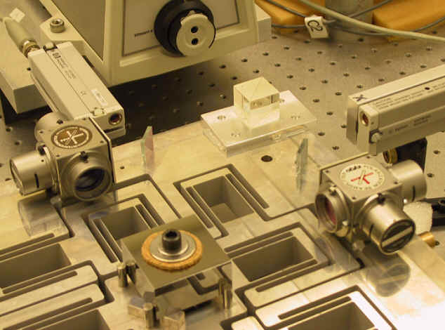
By now, you’re probably dying to know what all of those plus signs and vaguely cross-shaped things are doing in many of the pictures presented. No, we’re not all making ecclesiastical icons! Those crosses are what I’ve come to term "t-nuts".
What do you call these, anyway?
There’s not an industry standard for these things, and "t-nut" is just my shorthand name. Strictly speaking, "t-nut" or "tee nut" refers to a type of pointy nut you insert into wood to create a strong threaded hole. Alternatively, it goes into the T-slots of a machine table to anchor workpieces, vises, etc.
Many names have been proposed. Slotted-insert nut is one common name, because "insert nut" itself is already a type of nut. Crossed-T nut describes the shape of what you slide the nut into. Yes, I’ve heard them called Jesus Nuts. Captive slot nuts. Slotted nuts.
Regardless of what they are called, they are used to simulate a tapped hole in the edge of a workpiece by creating a slot into which you slide a machine screw nut.
It should be obvious why these are often used between two finger joints.By itself, the nut can easily deform away and burst the two narrow steps holding it in place under a tensile (pulling-out) load. However, if it is surrounded by finger joints, tensile loading forces will push the finger joints into their slots harder. *The tensile strength, then, is generally only limited by the pull-out strength of the screws. *
T-nuts and Constraint
Based on the previous statement, it can be seen why a slot and tabbed structure backed by T-nuts can actually be very strong. However, it’s important that the nuts be used in multiple planes on each joint and that the joints have proper bracing and gusseting to avoid "opening like a book".
The first image, a machine base by Daniel Fourie, clearly shows an open-finger-joint gusset, but with t-nuts facing into all of the planar surfaces such that the corner is very well constrained.
Flat-bottomed vs. Crossed
The first style of t-nut I used years ago was a parallel discovery. I realized while designing slots in a part to be waterjet-machined that I could widen the bottom of the slot, drop a nut in it, and have a fake tapped hole. This was a very exciting discovery that I used initially, and is in fact forever recorded in history in the How to Build Your Robot Really Really Fast.
However, later research led to me finding that this was in fact a common thing already. And that everyone elses was better: the fully crossed nut.
The reason flat-bottomed nuts are not as strong is because of the potential for the fastener to bottom out at the end of the slot. Screws are made with a length tolerance usually on the order of a hundredth of an inch (0.01", .25mm or so) or more. If the screw hits the bottom of the slot, it will "tighten" the nut against the opposing wall of the slot. But the rest of the screw, then, is without tension. If you design a flat bottomed T-nut to account for the longest screws, then you risk not engaging enough thread in the nut, again creating a weaker scenario. Imagine my disappointment when I discovered I was not the smartest person to have ever lived.
A fully crossed nut, as shown in the 1st and 3rd image, gives some leeway for screw length. The nut can be positioned within the known good lengths of screw thread, while the very tip is made longer than the worst-made screw. Taken to the extreme, the tip can extend even further so you stop caring what length* of screw *is used!
Critical Dimensions for your T-nuts
The fourth image (the one with actual numbers) is my usual CAD layout when putting in a t-nut. There are 5 critical dimensions, appropriately numbered.
- Fastening Length. I usually set this as the nominal length of screw to be used (e.g. 0.5"). This distance is measured from the top of the finger in a finger joint scenario, since screws are usually rated by the length under their heads.
- Thickness of Nut. This depends on the precise nut in use. Generally, this is a regular "finished machine screw nut", so standardized dimensions are available. (Is there such a thing as an unfinished nut?). Here’s another table that includes very small screws. The example dimension is 0.095", just barely above the nominal thickness of a U.S. #4-40 nut (which is 3/32", 0.0938" thick). Why 0.095? Find out in the next section!
- Clearance Width of Screw. Again a table-lookup operation, this should be the clearance hole you’d normally drill to pass a screw through. A screw size chart or tap drill chart is invaluable here. The example dimension is 0.120", a reasonably loose fit for a #4 screw.
- Width of Nut. This is usually the width across flats of a hex nut. However, in some materials, the thickness is less than the point-to-point width of the same nut. If a flat surface is needed, then this width must be the width across points. You can find out this dimension with a little bit of geometry. The example width is 0.25" for a #4-40 nut.
- Screw Clearance Depth. This length should be greater than the sloppiest screw in your collection. I often go up to 0.03 (1/32") over.
The rectangular profiles are vertical- or horizontal- constrained in the sketch, such that I could change the dimensions if needed without having to reposition them. Additionally, I usually give the dimensions meaningful names (e.g. NutThickness) and reuse it across many sketches.
Cautions
There’s some design "nonoptimalities" you can easily corner yourself in if you misapply the Art of the T-nut.
Bottom of slot is too close to material edge
Shown in image 5, one of Chibikart’s front bumper-splitter mounts, there’s a nut very close to the bottom of a slot. The area past the nut to the left has very little meaningful strength. The rectangular edges of these finger joints and t-nuts are basically stress risers and places for cracks to form. It is essential that the bottom of the nut be far from the edge of the material as a result.
Just how far is a matter of how the structure will be loaded. In a situation like image 6 (the U shaped piece) where the plate is backed up by being interlocked into many other plates near by, generally one screw diameter is my safe accepted minimum depth. This is because you can assume the material itself takes most of the loads (assuming the tabs and slots are tightly fitting), and very little is actually transferred into the screw.
However, in a longer beam situation like image 7, the material can deform much more, to the point where the screw and nut are not just providing a tensile load to keep the tabs and slots mated - the nut can actually be loaded against the inner walls of its slot. Being a square, inside edge, this is a great stress riser case study.
One way to get around this is to make "camel humps" where the bottoms of the slots are such that the stresses "flow" around the nut smoothly. The size of the "hump" should make it such that there is at least 1/2 material thickness between the corner of the slot and its closest edge.
Step 5: Making Boxes, Impossible Assemblies, and Edge Precedence
One of the most common things done with finger joints is to make little boxes and cases and other closed bodies. In fact, one of the first assignments at MIT’s well known "How to Build (Almost) Anything Class" is building a small laser cut press-fit thing (example student page). The process of making a box will also help address the importance of closed loops and gusseting in finger joint designs, a topic to be expounded on more in the next step.
Making a Box: Order of Assembly
It’s very easy to design yourself an assembly that is impossible to put together in real life if you do not explicitly think about the order in which parts will be put together. Pretty much all CAD programs let you move things into and through each other and edit parts exactly where they are, and it’s a trap that people fall into where they start making closed slots around. A closed slot necessitates a perpendicular motion to install the mating part. So, for instance, two parts at 90 degrees with closed slots such as Image 2 is physically impossible to assemble in one motion.
It is therefore critical to decompose your assembly process into discrete perpendicular movements, and come up with your own heuristic for deciding which sides take precedence over others. Here, I define precedence is defined as something which overlaps or fully encloses another piece. The quirk in my working definition is that these pieces get assembled last, but if you ever have to take the thing apart, they must be removed first.
For example, in Image 3 (of my board power test jig), the sides have the most precedence because they enclose all the other slots. They must be put on last, or taken off first, in order to service the device or change the pin layout, etc. An alternative intepretation is that the higher precedence parts can have other parts assembled onto them first - I could choose to mount the 3 inner faces onto one of the side plates first, then shove the other one over it.
Open Finger Joints are Easier to Assemble
The hazard of impossible assemblies is lessened when most of your joints are the open type. Because these do not completely envelop a tab in material, even a fully assembled box can be opened up again. The downside is that the faces are less well constrained and there is more reliance on fastener pressure to keep the assembly together.
In the 5th and 6th images (of Kitmotter’s little demo stand), notice the perpendicular fasteners on each face. There is no one face which only has side T-nut slots - if there were, it means that face would be dependent only on friction to hold it in place and could conceivably be pulled out.
Now, practically speaking, Kitmotter’s box is not a very strenuous structural application. However, a vehicle frame is - Image 7 shows the side of one of my quickly built scooters "Straight Razer" which only has perpendicular fasteners at the very front and rear of the frame. The middle, unfortunately, tended to bow out over time and with vibration. Even a few sideways fasteners could have prevented this.
The last four images concern the creation of a small, open jointed box. The box is built much like Kitmotter’s display stand - if it isn’t glued or welded, any of the parts could be taken off by itself to service in the insides.
Step 6: Cautions: Fits and Tolerances
If you go out right now and cut a 0.5" tab to fit in a 0.5" wide slot using an abrasive waterjet, it will take a few tons of force to mate the two parts together, after which they will never come apart again.
In contrast, if you laser cut two pieces of plastic or wood to the same dimensions, the fit will be so wobbly that you might have issues keeping your structure together as you’re trying to assemble it!
Why does this happen?
Process Tolerances
Abrasive waterjets suffer from tapered edges by nature of their cutting method: a noodle of highly pressurized water (The linked resource is an excellent read for anything regarding waterjetting technology, by the way). There are basically two major factors that contribute to waterjet manufacturing tolerances:
- Nozzle Offset and Wear. The machine controller for a waterjet will direct the nozzle at a preset distance such that it is nominally 1 stream radius away from the part. This is nozzle offset. In an ideal world, this gets you a part that’s exactly on dimension, but nozzles wear out. As they wear, the stream becomes more spread (losing precious pressure) and the nozzle itself gets larger. While this might seem to make the part smaller, the more dispersed jet is less able to direct its energy into the material, hence making cutting performance worse.
- Speed relative to material hardness and thickness. Preset cutting rates for materials and thicknesses are basically found empirically by the manufacturer. As described on waterjets.org, the faster the cut, the more taper and wavy edges will be seen, both causing part size deviations.
All this might sound terrible, but it is generally on the order of 0.005" (0.13mm) or less, per side. The trouble is that for most metals, 0.005" is a horrific interference and 0.01" is impossible. Plastics, being more deformable, may be able to handle it depending on their flexibility (brittle plastics will rupture at the inside corners). Much sanding and filing could be involved as a result, negating the quick assembly advantage.
For laser cutters, the biggest contributions to part slop are
- Focus. If the laser is cutting out of focus, then what should be a pinpoint of light becomes a gnarly wide beam, melting away more material than it should. It may not even cut through on the first try as a result, leaving an even wider kerf for future attempts. The 2nd picture shows the effects of being in focus and out of focus, for the same part. Look at the nasty melt on the left one!
- Part Thickness. Laser light is not a straight beam (collimated) at the cutting end, but is focused to a point. So, the thicker the material, the more in-and-out of focus the beam will get as it travels. Thicker materials will always cut messier.
In a laser process, the way to avoid these two phenomena is to use a long-focus lens so the part thickness matters less, and keep it in focus in the center of the material.
For typical shop 60-150W lasers, the beam width is on the order of 0.006" or less. The actual kerf of cut will depend on the material - plastics, for instance, will tend to keep melting after the cut, widening the kerf. Wood will remain stable. Adding in focusing effects, the kerf can typically be on the order of 0.01" or more.
But there is one advantage to using a laser cutter. The vast majority of common commercial machines cut on the line. That means no magic offset parameter, and the kerf is applied equally to both outside and inside dimensions. What this means is laser cutters will automagically enlarge your slots and shrink your tabs. I’ve heard of very few laser cutters which will compensate for kerf for you.
On the other hand, a router or mill, which uses a rigid cutting tool, is practically immune to both taper effects and uncontrollable kerf changes. You just get a naturally huge kerf compared to the other technologies, but rigid machines taking light cuts can hold tolerances to the thousandths of an inch, or at least within 0.003".
Material Tolerances
The machine is not the only source of errors which can stall your assembly process. Materials themselves are often not the dimensions they are sold as.
For example, the majority of "1/4" acrylic plastic is actually 6mm in thickness. 1/4" in decimals is 0.250" and 6mm is 0.236"! Hence, designing 1/4" wide slots and having 0.236" material will result in a very sloppy fit.
The manufacturing tolerances of metals and plastics also come into play. Most common laser cuttable plastics like acrylic are manufactured to a thickness tolerance of ± 0.02". This means a 0.250" nominal sheet could be as thin as 0.230 and as thick as 0.270 and still be sold you to as 0.25". Engineering plastics like Delrin (acetal) are made to tighter tolerances, such as ±0.005". (Source: McMaster-Carr).
For metals, the thickness tolerance depends on the material and manufacturing process. Rolled plates are usually slopper than precision-ground, but the latter is far more expensive. An example technical specification is found here for 1/4" 6061 aluminum plate - notice how the thickness tolerance varies with the finished thickness. For this 1/4" plate, the thickness tolerance is +/- 0.012".
I’ve personally dealt with 1/4" plate that was actually 0.265" and 3/8" (0.375) stock that was an amazing 0.390. At that point, I wondered if I bought 10mm aluminum (0.393) by accident! The third image is a picture of the side of my DIY Segway-like device, Segfault, in which I had to mill down some of the aluminum in the neighborhood of the finger joints because they just completely could not happen even with nozzle compensation - all due to material tolerances.
Mitigation
Compensating for kerf and taper depends on the technology. The most foolproof way is to make no assumptions and make a ‘kerf gauge’ which is a piece with several variations on your critical dimension. An example is shown in the fourth image. This piece has a few slots and tabs of increasing width, hovering around 0.5". Cut the piece on your machine of choice (or have it made) and measure the exact dimensions that come back. This establishes a metric for adjusting part tolerances for that machine and that material.
For example, with a gauge made with waterjet machining, the dimensions may be spot-on on one side of the cut, but be a few thousandths larger per edge (meaning your 0.500" test slot could be as small as 0.490" in places). For laser cutting, it might be the opposite - the material where the laser is least in focus, for instance, may cause the slot to be 0.515".
With this information, you can "design out" the difference in CAD software. Shown in the fifth image is an example of a slot being designed "on size" initially, then at the end offset outlines are drawn around the slots and compensation applied atomically in one extrude or Boolean geometry operation.
The same can be said of circular mating parts like sprockets and gears. In this case, the "free with service" slop of laser cutters is beneficial - gears, pulleys, and sprockets that are too small will just act like worn out regular ones. But the waterjet taper will absolutely kill your gear & sprocket fits! The last two images show fitting vs. nonfitting sprockets. On the fitting sprocket, I performed an offset operation on the entire sprocket profile that shifted the teeth inward by 0.005".
On parts which I do not know beforehand the specifications of the machine that will be used to construct it, I leave things extra sloppy and depend completely on good structural design and fastener use to retain rigidity. One example is the panels for the Democratic People’s Republic of Chibikart. On those, I went as far as 0.01" bigger on holes and 0.015" on slots to be safe!
The Bottom Line
Waterjets try to make your part exactly to size, but might end up making inside cuts (e.g. slots and holes) too small and outside cuts too large (e.g. tabs and profiles), making the part have too much material to fit without compensation.
Lasers cut on the line, making inside cuts larger and outside cuts smaller, but could end up making the final part too sloppy without compensation.
Ultimately, machines with rigid tools like routers and mills can still hold the best tolerances, but even then, your material might be sloppily made and too thick or thin.
Also, don’t just take my word for it - UPenn MEAM also has a few thoughts on the topic.
Step 7: Cautions: Open Loops and How to Strengthen Them
A classic newbie error I have witnessed personally from people using finger jointed plate construction is leaving flaps of material to try and stand on their own. This is a very easily encountered pitfall of this kind of construction. While joints relying on a third intermediate joining member like angle irons or L-brackets can use the manufactured perpendicularity, care is needed when directly joining plates together, no matter if they are laser-cut, waterjetted, machined via router, or carved out using your own teeth.
Thinking like a sheet metal fabricator, with skillful use of gussets and imitating "I" or "H" profiles, is essential for maintaining rigidity in assemblies. The fact of the matter is, long spans of plate or sheet are always going to be floppy unless backed up by something out-of-plane with it - i.e. turning moment loads ("bending") into tension and compression as much as possible, where most materials are the strongest.
So, I’m here to illustrate several potential failure points of this style of design as well as how to shore up your design against them.
Effect of Edge Taper on Right-Angle Fastened Plates
Shown in the introductory graphic is the classical failure mode. Because of the edge irregularities that lasers and waterjets tend to generate, you cannot assume the sides of the plate are truly perpendicular. The only way to eliminate this positively is with dynamic head or tilting head machines, which are much more expensive. And notice how the specification even says "virtually" eliminates taper - taper-free is defined as 1 degree of taper, and a usual waterjet or badly focused laser cutter will produce something more like 2 or 3 degrees.
Well, a 1 degree error on an edge translates through Abbe error magnification on a 10cm (4") long part to mean an offset at the top of nearly 2mm (.08"). This might not sound that bad except to engineering professors, but it’s very visible to the human eye, and furthermore an unsupported edge like that is much weaker than a supported one (remember Step 2?). If the taper is really bad, like 3 degrees, then the part is going to be out 6mm (1/4") or more at the top. Now that is truly horrible.
Hence, the lesson here is to never depend on a cut edge for alignment if it was made with a nonrigid process, e.g. laser or waterjet. The only way to be sure is to produce the part on a router or mill that is known to be perpendicular, known as being "in tram".
Next, we tackle the stiffness issue, or why your unsupported structure is so wubby.
A Typical Two-Plate Structural Element
Image 2 depicts a fairly typical two plate parallel structure that you might find on a robot or some other mechanical implement. At the end, it has a pin or shaft upon which another element, like the next arm segment, or wheel, rides. In the best case, this is tightened against the sidewalls with fasteners, but not infinitely stiff, so it will bend only in the middle. We assume the base is absolutely rigid and firmly attached to whatever this mechanism goes on, so there is no deformation at the base.
Image 3 shows a sideways 10 pounds of force ("lbforce"). Engineering purists would say that this is a fake unit and that I should really say 44 newtons, but for the sake of easier audience connection I’m going to assume most people know what roughly 10 pounds (or 5 kilograms) feels like.
Units aside, the finite element simulation shows the structure deforming sideways with the walls remaining roughly parallel. The total magnitude of the deformation is actually quite low (0.004" or so), but we will see it is the relative stiffness that counts. The shape is exaggerated on purpose by the simulation to show the final shape of the assembly.
Adding Flanges
One method that can stiffen the structure in the configuration is adding flanges to the sides. Think a "c-channel" or similar. The 4th image shows this example structure, and the 5th image is the results of the simulation with the same force magnitude and location. The simulation shows that this arrangement is already about 3 times as stiff as the original.
Depending on the geometry of the flanges, this relative value could be much more. Notice that they also do not reach quite as far as the location of force application and that the vast majority This was done because of a practical concern, since whatever it is supporting could take up enough space that extending the flanges all the way out is impossible. It therefore represents an example "middle ground" which you are more likely to encounter.
The example’s real-life embodiment is the scooter fork shown in image 6. This example only has one flange (like a T-extrusion), but the concept is the same: without it, the two 1/8" rear forks will be extremely wobbly indeed. This structure also sees forces more on the order of 100+ pounds, instead of 10, because of rider weight, cornering, etc.
Adding a Crossing Member
Another tactic is adding what is known as a web. In structural products parlance, the web is the middle of an I-beam, the element that reaches across the two sides. In the 7th image,the web is depicted as the flat plate in the center. Again, it is made to not quite reach the point of force application out of an example practical concern. For instance, an attached arm joint has a hub which is that large, so the web needs to be further away from the shaft.
Even with the end not well supported, the web configuration is the stiffest of them all - 7 times better than the original!
This is why buildings are made from I-beams.
A great example of using an intermediate web is the 4-bar manipulator arm of my own 2.007 robot, shown in image 8. This arrangement was, unfortunately, only of limited effectiveness because there was still a vast unsupported span in front of the grabber end, letting it flex in a similar manner to image 7. Additionally, I neglected to make a second one of those plates - leaving the bottom very poorly supported. As a result, the arm still moved significantly side to side under applied loads, but fortunately this did not affect the robot operation much.
Closed Loop Flexures
The overarching theme is to avoid using materials, especially thin plates, in bending. Support them with material that is out of the bending plane such that the loads are transferred to them and put them in tension or compression. The remaining few pictures are other examples of things being designed to resist wobbling, for better or for worse.
Making structures like those shown in the original FEA simulation in image 3 is an entire science on its own, and the creations are known as flexure bearings (another example, see figure 2). The neat thing about materials in bending is that they are generally very predictable if the deformations are small, so flexures are valued for their repeatability and immunity from "stiction" that a normal hinge could suffer from. They are found in precision machines and instruments for supporting sensitive adjustments.
Step 8: Nutstrip, Uber-nuts, and Corner Blocks
But what if I don’t have access to a laser cutter or waterjet, or can’t hire it out? Don’t worry, these next few sections are well-suited to garage builders, and much of it was how Yours Truly was able to build consistent robots for years.
Without a freeform 2D fabrication process, the square edges of finger joints are extremely hard and time consuming to make. Usually, it’s not worthwhile at all because other methods of fastening exist.
Nutstrip
It is fairly common for builders to attach 2 plates at right angles, contacting eachother (a Tee joint). Most often, this is done with an angle stock in aluminum or steel. If the stock is thick enough, end tapping, or drilling straight into the thickness of the material and cutting threads into it, is another common tactic.
Another method which can be versatile is known as "nutstrip". Typically it takes the form of an extruded barstock, for known square sides and size standardization, drilled and tapped at regular intervals. In the past, they were DIY items - literally made by hobbyists on mills and drill presses, but these days they can be purchased stock on sites like Kitbots or ServoCity, among others. However, if you can obtain small barstock economically, they are still easily made on drill presses.
Nutstrip is the most helpful when the plates being joined are of roughly the same thickness as the nut’s square dimensions. In this case, it can offer increased rigidity over using a thinner angle-stock-based right angle joint. In cases where the stock being fastened is very thin, then the angle stock is generally of a greater surface area and hence stiffer. However, watch out - the rest of the structure can be floppy!
Uber-Nut
A nickname for a single-row-tapped nutstrip that takes the place of individual nuts. The highly increased surface area of an "uber nut" compared to multiple discrete nuts makes the joint stiffer. This is helpful in situations where the mounting substrate is very flexible