For color mixing, this means visualizing all three color dimensions simultaneously as you work. The tool for this is a color space: a 3D coordinate system where every possible color occupies a unique position. There are a wide variety of color spaces, but the ones that matter for painting are those that are perceptually accurate. That’s because transitions between colors end up informing mixing decisions.
But seeing spaces only really work when they’re seamlessly integrated into the user’s environment. They must also be highly responsive and conceptually powerful. That’s a lot to ask from a smartphone, tablet or desktop. None of these devices can be integrated into the painting flow without disrupting it.
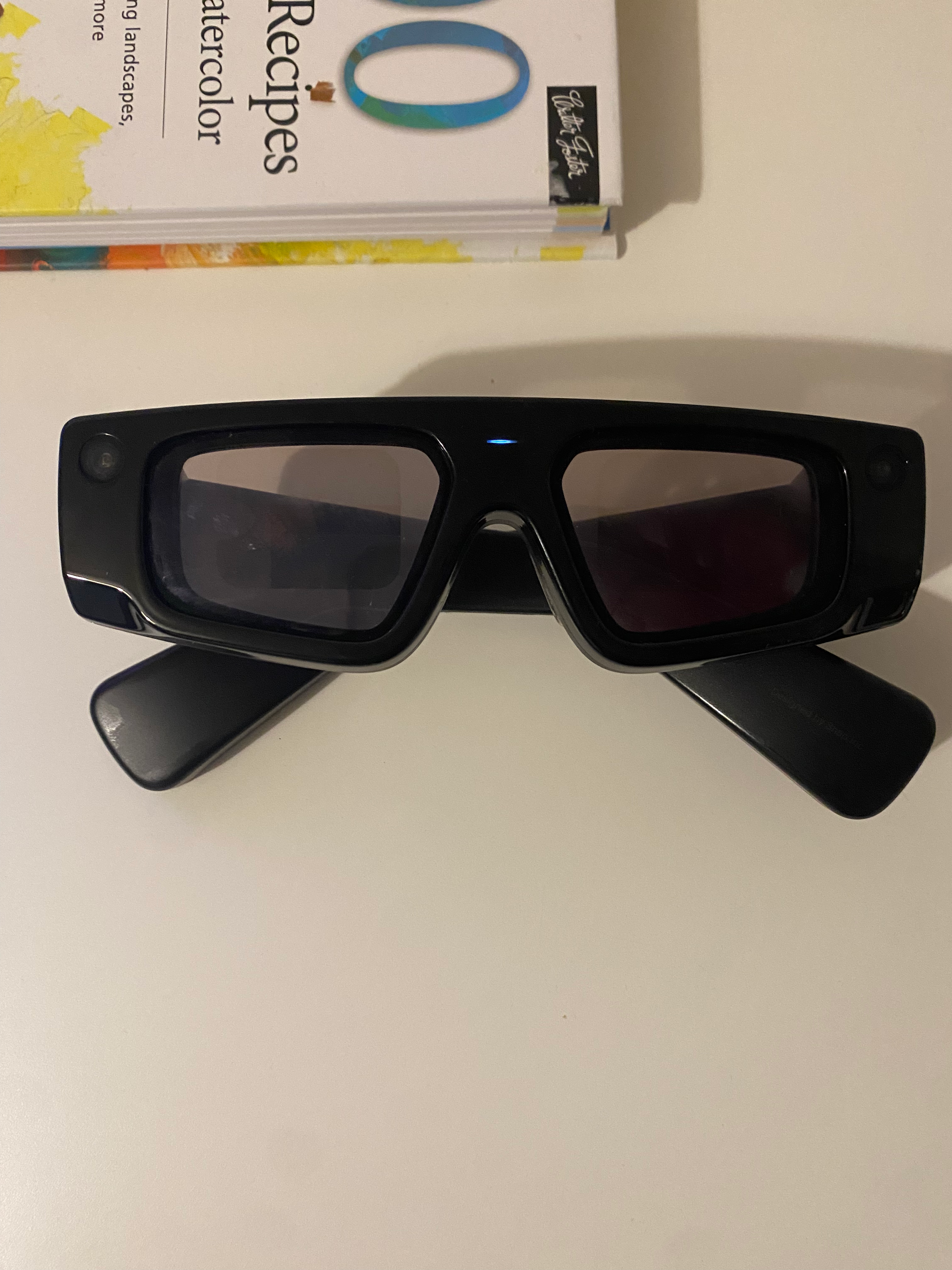
Luckily, we are entering the age of AR glasses and I got a pair of [Spect…
For color mixing, this means visualizing all three color dimensions simultaneously as you work. The tool for this is a color space: a 3D coordinate system where every possible color occupies a unique position. There are a wide variety of color spaces, but the ones that matter for painting are those that are perceptually accurate. That’s because transitions between colors end up informing mixing decisions.
But seeing spaces only really work when they’re seamlessly integrated into the user’s environment. They must also be highly responsive and conceptually powerful. That’s a lot to ask from a smartphone, tablet or desktop. None of these devices can be integrated into the painting flow without disrupting it.
Luckily, we are entering the age of AR glasses and I got a pair of Spectacles.
With the hardware sorted, I needed to decide what exactly to visualize. I had three goals in mind:
- See where a color on my palette sits in the color space, so when I change its mixture, I can track the result.
- See which colors are reachable by mixing my available pigments, via what is called a color gamut.
- See how a target color maps onto my gamut: what’s the closest I can get to a reference color with my pigments?
The sRGB space, which we’ll improperly abbreviate as RGB, is the obvious starting point, but because of its perceptual inaccuracy, it’s a poor fit for this problem.
CIELAB, for instance, is better suited: it’s designed so that equal distances in the space correspond to equal perceived color differences. This is also an intuitive choice for painters who are generally familiar with Munsell Color System. CIELAB works the same way: lightness on the vertical axis, hue as rotation, and saturation as distance from center.
Next, I needed to figure out how to render this space. Solid meshes only show the surface, and volume raymarching is too expensive for AR (which renders stereo at 1.5x normal framerates). So I turned to particles.
VFX Particles
I’ll tell you one thing: Lens Studio’s VFX Editor is fun to use. It’s like a stylish combo of Unity’s Visual Effects Graph and Blender’s GeoNode Editor with some sparks of Houdini VOP brilliance.
Now, it doesn’t come without its own quirks, especially regarding my use case.
The main challenge was encoding the position of every element of the color space so that it could be read by the VFX editor and used to modify particle attributes.
Figuring out a good encoding strategy was tricky. I stumbled on the lack of support for floating point textures in Lens Studio 5.15. Fortunately, the tutorial Spawn Particles on Mesh helped with this. I also had to deal with a peculiarity where the integer index of particles in the VFX Editor is always even. As a result, I had to spawn twice as many particles as those actually displayed. This was painful to debug, but eventually I settled on a suitable workflow.
The encoder material writes position and color data into render textures. The script orchestrates the pipeline, creating render targets and connecting the material output to the VFX input. Finally, the VFX decoder spawns particles, sampling the render textures to set each particle’s position and color.
Here’s the result:
Now, as happy as I was to have overcome those technical hurdles, the performance just wasn’t there. Adding 3 such VFX to my scene would visibly reduce framerate, which drastically deteriorates user experience. Rendering particles as billboard quads instead of 3D meshes helped, but the improvement wasn’t satisfactory.
At this point I hit a wall. As it happened, I had to travel to Brussels and Eindhoven for UnitedXR and the Spectacles x 3EALITY hackathon, which gave me a chance to step away from the problem.
When I came back, it hit me: color spaces have interesting regularities. The mapping from RGB to LAB is continuous. In other words, nearby colors stay nearby. The math behind it is juicy but put simply, if you render grid lines for an RGB cube, you can deform them into LAB space and they’ll stretch and bend, but never break.
Here’s a manim visualization that showcases this process:

View manim source
It was clear then that I didn’t need a system as flexible as VFX particles to accommodate any arbitrary spatial layout. I could "simply" define one layout and deform it to achieve the others.
Procedural Meshes
In Lens Studio, you can create meshes procedurally. Using the MeshBuilder API, you can specify vertex positions and store any attribute you like. Then, you can assign a material that alters the position of those vertices. When I tried this, I was mindblown by the performance improvement.
Though the procedural mesh generation was quite delicate, once done I could essentially let my imagination run wild. And since vertices are looped over in the GPU via vertex shaders, I didn’t have to worry about their count.
To make the process of low-level geometry construction and manipulation more, let’s say… humane, I used a coding agent supplemented with a Custom Code Node specification.
I initially went for lines. It came up as a good balance of volumetric space-filling and low polycount.
Then, I tried spawning cubes and repositioning their vertices. The performance was great, much better than VFX particles rendered as cube meshes. I suspect this is due to memory allocation niceties of the MeshBuilder API, coupled with not creating any new geometry at runtime.
Having cleared a path towards seamless rendering of color spaces, I could now tackle the painting workflow pain points mentioned earlier.
Full Color Space
The complete CIELAB color space, rendered as a grid of cubes. We can now see the full range of perceivable colors and where any given color sits within it. Solves Problem 1.
Pigment Mixing Gamut
This workflow computes the gamut of a set of pigments via three-way subtractive mixing. With it, we can see which colors are achievable with a given palette. Solves Problem 2.
Pigment Projection
This workflow projects a color onto the gamut boundary. Given a set of pigments and a target color, we now know in advance which achievable color is closest. Solves Problem 3.
And one final demo in-editor, because we can’t go out there not looking good.
In Part 1, we saw how to sample colors from our environment, which gives us the colors on our palette. In Part 2, we’ve managed to see, via computational tools, where those pigments can take us.
But this is still too abstract. We need additional steps to blend these seeing spaces into a coherent user experience.
Ideally, we’d like to preview the scene around us under the constraint of the pigments at our disposal, and have our assistant guide us towards achieving something close to our reference without disrupting our flow or limiting our creative freedom.