Published December 8, 2025 © MIT
Motor Driver Patch is a DIY H-bridge-based dual motor driver featuring 8 N-channel MOSFET ICs connected in an H-bridge configuration.
BeginnerFull instructions provided1 hour**11

Things used in this project
Story
Greetings, everyone, and welcome back.
1 / 4
Here’s something fun I’ve been working on, the Motor Driver Patch, a small DIY dual motor driver board that I built …
Published December 8, 2025 © MIT
Motor Driver Patch is a DIY H-bridge-based dual motor driver featuring 8 N-channel MOSFET ICs connected in an H-bridge configuration.
BeginnerFull instructions provided1 hour**11
Things used in this project
Story
Greetings, everyone, and welcome back.
1 / 4
Here’s something fun I’ve been working on, the Motor Driver Patch, a small DIY dual motor driver board that I built completely from scratch. It uses eight N-channel MOSFETs, four for each motor arranged in an H-bridge setup. The MOSFETs work in pairs: when one pair is switched on, the current flows in one direction and the motor spins that way; toggle the opposite pair, and the motor reverses.
The whole idea behind this project was to make my own MOSFET-based H-bridge motor driver instead of relying on modules like the L293D or L298N. I wanted something I could drop directly into my own PCB designs, especially for a robot rover project I’m building soon. Space is tight on that rover, so I’ve been experimenting with compact drivers—and at some point I thought, why not just make my own?
So this article is basically the process of how I designed and built this little motor driver from scratch. Let’s jump into how it all came together.
MATERIALS REQUIRED
These were the components I used in this build:
- Custom PCBs (provided by JLCPCB and JLCCNC)
- A04406 Mosfet IC
- 10K Resistor
- 5R1 Resistor
- CON6 vertical male header pin
- CON2 JST connector
- 5V operating Gear Motor
- Breadboard
- Push Buttons
- Connecting wires
- Microcontroller—XIAO ESP32 C6 (any MCU can be use here)
CIRCUIT
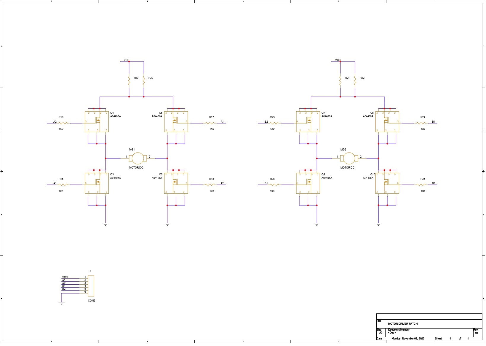
We first started by preparing the schematic for the project, and the design is fairly simple. The core of the circuit is an H-bridge made using four AO4406 N-channel MOSFET ICs—MOSFET 1, MOSFET 2, MOSFET 3, and MOSFET 4—with the motor placed in the middle.
MOSFET 1 and MOSFET 2 form the high-side pair. The drains of both are tied together and connected to VCC. Their sources go to the two terminals of the motor.
On the low side, the drain of MOSFET 3 connects to the same motor terminal as the source of MOSFET 1, and the drain of MOSFET 4 connects to the motor terminal paired with the source of MOSFET 2. The sources of MOSFETs 3 and 4 are both tied to GND.
Each MOSFET gate is paired with a 10K resistor. The gates of MOSFET 1 and MOSFET 4 share one input line, while the gates of MOSFET 2 and MOSFET 3 are linked together on the second input line. These two inputs act as A1 and A2. By toggling A1 and A2 HIGH or LOW, we decide the direction of current flow through the motor, which in turn controls the rotation direction.
We then duplicated this entire H-bridge to create a second identical driver for the second motor.
To keep everything neatly connected, we added a CON6 header that brings out VCC, GND, the two inputs for Motor 1 (A1 and A2), and the two inputs for Motor 2 (B1 and B2).
PCB DESIGN
1 / 3
The PCB design for this project was pretty straightforward. Once the schematic was ready, I exported the netlist into my PCB editor and started by creating a simple square outline for the board. From there, I began arranging all the SMD components inside that space, starting with the H-bridge MOSFETs for Motor 1 and Motor 2, placing them in the correct layout.
The resistors linked to the MOSFETs for Motor 1 were placed right next to that set, and the same for the resistors for Motor 2. The load resistors, which use a 2512 package, were placed on the top side above the MOSFETs. After that, I routed all the traces, making sure to keep the VCC and GND lines thick, along with the traces leading to both motor connectors—just to handle current properly.
Once the layout was finalized, I added a few aesthetic touches too, like small dots, outlines around components, and other simple details on the top silkscreen to make the board look a bit nicer.
JLCPCB SERVICE
1 / 3
Once the board design was finalized, I went ahead with a purple solder mask and white silkscreen and uploaded the Gerber files to JLCPCB’s quote page. I usually choose white or black for most of my builds, but this time I wanted to switch things up, and the purple option looked too good to skip.
I’ve tried PCB services from a bunch of different companies over the years, but JLCPCB’s quality still feels a step above the rest. The ordering experience was smooth, the pricing was solid, and the boards showed up in under a week. When I finally checked them out, the finish was clean, the silkscreen was sharp, and everything aligned perfectly with my design. The purple solder mask especially stood out—it gives the board a nice, premium look.
It’s also worth mentioning that JLCPCB has a dedicated CNC and machining division, JLCCNC which assisted us in preparing this project.
If you’re working on enclosures, brackets, or any custom mechanical parts, JLCCNC handles CNC machining, milling, metal fabrication, and even custom cutouts with the same level of quality and consistency JLCPCB is known for. It’s pretty convenient when your PCB and mechanical parts can come from the same ecosystem.
Overall, the boards turned out great, and experimenting with the purple solder mask was totally worth it.
PCB ASSEMBLY
1 / 6
- After unboxing the PCBs, we began the assembly process, which was quite straightforward. We first applied solder paste to each component pad using a solder-paste dispensing syringe. For this build, we used Sn/Pb-63/37 solder paste, which melts at around 200°C.
- Once the paste was applied, we gathered all the SMD components (MOSFETs, resistors, and other parts) and started placing them on the board using tweezers. For MOSFET ICs, we paid special attention to the orientation, aligning each one with the dot marked on the silkscreen to ensure they were placed correctly.
- With all components positioned, we carefully lifted the PCB and placed it onto our Miniware reflow hot plate. The hot plate heats the board from below, and as the temperature gradually rises to about 200°C, the solder paste melts and securely holds every component in place.
- After the reflow process, we moved on to the through-hole components. We added the two JST connectors for the motor on the bottom side of the board, along with a CON6 male header pin that allows the board to be plugged into a breadboard. Flipping the PCB over, we soldered all the JST and header pins using a standard soldering iron, completing the assembly.
MOTOR and POWER SOURCE
1 / 2
Before moving on to testing the driver, we’re using a DC gear motor rated for 3V to 12V as our test motor. For the power supply, we’re using DFROBOT’s Rainbowlink 4, which serves as a USB converter for multi-channel serial communication and power output. By connecting it to a PD adapter, we’re able to get a stable 5V to power our entire setup.
BREADBOARD VERSION LEVEL 1
1 / 5
We now move on to testing our homebrew motor driver, starting with a simple breadboard setup.
The driver is based on an H-bridge configuration, where two MOSFETs work together to control the direction of current flow. The motor’s rotation and speed are managed through two gate inputs. For Motor A, we use pins A1 and A2—setting A1 HIGH and A2 LOW spins the motor in one direction, and reversing the logic (A1 LOW and A2 HIGH) flips the rotation.
For the breadboard test, we placed two buttons on the left and two on the right side of the motor driver. Button 1 is connected to A1 and VCC, while Button 2 goes to A2 and GND. On the right side, Button 3 connects A1 to GND, and Button 4 connects A2 to VCC. Pressing Button 1 and Button 2 together completes the circuit and drives the motor in one direction. Pressing Button 3 and Button 4 instead reverses the connections, causing the motor to spin the opposite way.
DUAL MOTOR LEVEL 2
1 / 3
Next, we added the second motor to the Motor Driver Patch and placed another set of four push buttons for the B1 and B2 pins. The wiring is the same as before: two buttons on the left and two on the right. Button 5 connects to B1 and VCC, and Button 6 connects to B2 and GND. On the opposite side, Button 7 goes to B1 and GND, while Button 8 connects to B2 and VCC.
Just like the first motor, pressing Button 5 and Button 6 makes the motor spin in one direction. Pressing Button 7 and Button 8 reverses the current flow, causing the motor to rotate the other way. With this setup, we were able to confirm that both motor channels are working exactly as expected.
MICROCONTROLLER LEVEL 3
1 / 2
Now comes the main test of this whole project—pairing the Motor Driver Patch with a microcontroller. For this, I decided to use a Seeed XIAO ESP32-C6 and connected A1 and A2 to GPIO0 and GPIO1. But the moment I uploaded the test sketch and powered everything up… nothing happened.
The reason turned out to be something I completely overlooked at first: the MCU’s GPIO pins weren’t providing a high enough signal. The XIAO outputs less than 3.3V on its pins, while the MOSFETs on our driver need at least a solid 5V to properly switch their gates. So essentially, the MOSFETs never toggled, which meant the motor wouldn’t move at all.
To fix this, the humble BC547 transistor came to the rescue. I added two of them in a simple transistor-switch configuration, one transistor to pull A1 up to VCC and the other to pull A2 down to GND. With this setup acting as a level shifter, the MCU could finally control the MOSFET gates properly, and the motor driver responded exactly the way it should.
Now that this issue has shown up, it’s clear that the next revision of the Motor Driver Patch needs to include these transistors built directly into the board. That way, any MCU—3.3V or 5V—can drive the H-bridge without extra wiring or modifications.
CONCLUSION
1 / 2
The motor driver performed well overall, though we did encounter one limitation: the microcontroller couldn’t drive the input pins directly since it outputs only 3.3V, while the driver requires at least a 5V signal.
To solve this, we used transistors to shift the 3.3V signals up to 5V and pull the pins properly to HIGH or LOW, allowing reliable control of the MOSFETs. In the next revision of this project, we plan to integrate this transistor stage directly into the H-bridge design so the driver can be easily controlled by any microcontroller.
For now, the project is complete, and all related files and details are provided on this article page. If you run into any issues, feel free to reach out.
Stay tuned for the upcoming update.
Thanks for reaching this far, and I will be back with a new project pretty soon.
Peace.
**Read more
Schematics