In HackerBox 0118 More Human I talked about BLE and WiFi scanning using Arduino. In HackerBox 0119 Geopositioning I talked about using a GNSS with an ESP32. In Testing Out BLE Beacons With beaconDB I set up some BLE beacons around my house. What on earth am I up to?
Well, after switching to GrapheneOS I’ve been thinking about alternatives for power efficient location tracking. The modern position tracking system provided by Google Play Services is really cool in terms of how …
In HackerBox 0118 More Human I talked about BLE and WiFi scanning using Arduino. In HackerBox 0119 Geopositioning I talked about using a GNSS with an ESP32. In Testing Out BLE Beacons With beaconDB I set up some BLE beacons around my house. What on earth am I up to?
Well, after switching to GrapheneOS I’ve been thinking about alternatives for power efficient location tracking. The modern position tracking system provided by Google Play Services is really cool in terms of how they balance power and accuracy. I want to do a piece breaking that down, but I’ll wait for a future post.
Anyways, beaconDB is a really interesting project for crowd sourcing cell tower, BLE Beacon and WiFi access point observations. I’ve been contributing observations using the Neostumbler app, but there is a noticeable battery impact. The app has a passive mode that only records observations when other apps on the phone request location, however that cannot be used on GrapheneOS.
Regardless, Neostumbler got me thinking about whether I could build a low power device to continually collect observations. I had been looking at different hardware to use, but lucked out when I got a Tiny Yeti Locator (TYL) from HackerBox 0119.
In the long term I’m aiming to use Rust and Embassy for this project, but the Rust HAL does not support WiFi and BLE for the ESP32 dev board the TYL uses:
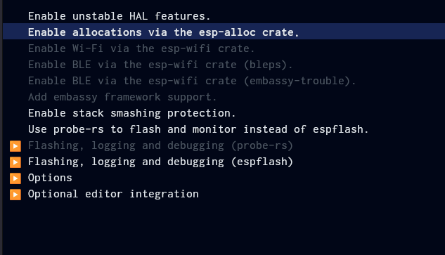
So for now I thought I would do the quickest and dirtiest prototype using what I have. The code is available in this repository.
Here is what I ended up doing for the prototype:
-
Get GNSS updates.
-
Synchronize clock time with the GPS time.
-
Scan for nearby BLE devices.
-
Filter for just BLE Beacons.
-
Scan for nearby WiFi APs.
-
Write all observations to the SD card.
Its been a minute since I used C++ and man Arduino is weird.
Since I’m not in Rust land for this project I need to shake off some dust. I haven’t written C++ since I was in middle school. To add to the confusion Arduino is just weird:
- As the code base grew I wanted to use multiple files. In Arduino they get concatenated in alphabetical order.
- I don’t see good API docs for standard libs.
- No declarative package management or lock files. Instead everything is installed through the UI.
- I inconsistently see PascalCase for method names in examples.
A note on AI assistance in this project:
I try really hard to make sure everything I post on this blog and represent as my own work is my own work. So:
- This project slams together a lot of example sketches others have written. I make sure to call out the original files when I reference them.
- Since this project involved exploring a new set of tools I am not familiar with, I bounced ideas off of Claude Code. I had Claude configure the CLAUDE.md to explicitly state I only want feedback on questions I ask and not to have Claude modify my code for me:
## Working with this Project

This is a learning project. When interacting with this codebase:
- **Wait for the user to ask** for help, feedback, or explanations
- **Do not proactively suggest** code changes or tell the user what to code
- **Provide guidance when requested**: Answer questions about the code, explain implementation details, help debug issues, or review code when asked
- **Be responsive, not directive**: The user is learning and wants to drive their own development process
If you see poor quality code in this project, that’s all me.
Starting with the TYL GPS test as a baseline
In the Instrutables for HackerBox 0119 they provide a TYL_GPS_Test.ino example sketch. The file provided examples of two important parts:
- Setting up and using the TFT screen on the board,
- Setting up and getting the location from the GNSS chip.
I moved the GPS related logic into its own file. For each piece of this project I roughly had the following:
- A setup method the main setup method would call.
- A method to write an observation to the SD card.
The GPS logic is in this file. The setup code is very similar to what I covered in HackerBox 0119, so I won’t rehash that here.
Adding BLE Beacon Scanning
So what are BLE Beacons? I made a whole separate post Testing Out BLE Beacons With BeaconDB, that covers the topic already.
The Arduino IDE includes a number of examples built in. The set of examples changes based on the board module you are using, so they are often hardware specific. Under File -> Examples -> BLE there is the BeaconScanner example I used as a reference. The main parts I learned from the examples are:
- Configuring the device for BLE scans.
- Creating a BLEAdvertisedDeviceCallbacks to handle receiving BLE device advertisements.
There are different types of BLE beacons. To tell them apart you need to parse the BLE payload. The beacon scanning example for Arduino was a good reference for telling apart iBeacons, EddystoneURL, and EddystoneTLM beacons. However, I don’t actually need the information in the beacon payload.
I only needed to know if a BLE device is a beacon, so I can filter out the non beacon BLE devices, because the beaconDB API only wants BLE beacons. So I simplified the checks to:
bool isBeacon(BLEAdvertisedDevice advertisedDevice) {
if (advertisedDevice.haveManufacturerData() == true) {
return false;
}

String strManufacturerData = advertisedDevice.getManufacturerData();

// Buffer to store manufacturer data (BLE max is 255 bytes)
uint8_t cManufacturerData[255];
size_t dataLength = strManufacturerData.length();

if (dataLength > sizeof(cManufacturerData)) {
return false;
}

memcpy(cManufacturerData, strManufacturerData.c_str(), dataLength);

if (dataLength == 25 && cManufacturerData[0] == 0x4C && cManufacturerData[1] == 0x00) {
// iBeacon
return true;
} else if (advertisedDevice.getFrameType() == BLE_EDDYSTONE_URL_FRAME) {
return true;
} else if (advertisedDevice.getFrameType() == BLE_EDDYSTONE_TLM_FRAME) {
return true;
}

return false;
}
Similar to handling GPS, I moved the BLE logic into its own file which you can see in ble.ino.
On debugging and serial out
All of the Arduino examples do debug logging over hardware USB serial. However the TYL maps the GPS_RX pin to GPIO1 and GPS_TX to GPIO3, which is necessary for USB serial to work, so I cannot use the serial monitor for debugging. During testing I had to change all debug lines to printout information on the TFT display.
Additionally I wanted to use different areas of the screen for different pieces of information:
tft.fillRect(0, 100, 320, 100, ILI9341_BLACK);
tft.setCursor(0, 100);
fillRect allowed me to clear parts of the screen while keeping text on others. Then setCursor let me print to the specific part of the screen I just cleared.
Now ironically, in HackerBox 1120 Current Affairs I recently received a USB-to-serial adapter, so I suppose in the future I can learn how to make a software serial work.
The TFT setup code is available in tft.ino.
Adding WiFi AP Scanning
Next up was adding support for scanning WiFi access points. In the Arduino IDE under File -> Examples -> WiFi there is WiFiScan.ino. The main parts I learned from the example are:
- The ESP32 Arduino WiFi library can operate in two modes: working as an access point or working as a station. In my case I wanted to make sure the device was in station mode.
- Setup is a simple as a call to
WiFi.STA.begin();. - To get scan results I had to make a call to
WiFi.scanNetworks();and then iterating over the devices by index.
This small example demonstrates how the iteration over the found networks works:
void scanWiFi() {
int n = WiFi.scanNetworks();
long scanTime = millis();
...
if (n != 0) {
for (int i = 0; i < n; ++i) {
// access information with WiFi.SSID(i).c_str()
}
WiFi.scanDelete();
}
}
Also, the example code uses pre-processor conditions based on ESP_IDF_VERSION to handle devices that support both 2.4ghz and 5ghz bands for WiFi. In my case the TYL only supports 2.4ghz so I removed the pre-processor code.
I added in some WiFi code and all was good... or not. I started to get the following build error:
Sketch uses 1696115 bytes (129%) of program storage space. Maximum is 1310720 bytes.
Global variables use 61196 bytes (18%) of dynamic memory, leaving 266484 bytes for local variables. Maximum is 327680 bytes.
Sketch too big; see https://support.arduino.cc/hc/en-us/articles/360013825179 for tips on reducing it.
text section exceeds available space in board

Compilation error: text section exceeds available space in board
There is a limited amount of space on the ESP32 for storing programs. It is not uncommon to run out of space when trying to use both the WiFi and BLE libraries. [1] For this prototype I ended up switching the partition scheme to “Huge APP (3MB No OTA/1MB SPIFFS)” in order to fit both libraries.
Another interesting thing I learned is that technically the ESP32 doesn’t allow WiFi and Bluetooth at the same time. Since both Bluetooth and WiFi share the same antenna and radio, there is some multiplexing happening. Thankfully, in my case I am only scanning for devices rather than keeping connections open.
You can see the full WiFi handling file in wifi.ino.
Saving CSV files to the SD Card and learning about SPI
The examples so far do not include any file I/O. The Instructables also includes a TYL_GPS_Map.ino example that reads from the SD card, but all of the file logic was abstracted by the Adafruit_ImageReader library. In my case I need to write to an SD card, so I have the opportunity to learn how that works.
The TYL uses a Adafruit ILI9341 based display with a built in SD card slot. [2]. The ESP32 communicates with the SD card over an SPI interface. This was my first time using SPI and I found a clear written guide about how SPI works. Additionally, this is a nice video comparing UART, I2C and SPI which was useful since in HackerBox 0119 I got to learn about how I2C works. [3] [4]
Anyways, the Instructables guide gives the following pinout without explanation:
SD_MISO 19
SD_MOSI 23
SD_SCK 18
SD_CS 5
As noted in the written SPI guide, the names for the pins are not universal so you sometimes you need to translate:
- Master Output Slave Input (MOSI), allows the main chip to receive data from the connected chips.
- Master Input Slave Output (MISO), allows the connected devices to send data to the main chip.
- Serial Clock (SCK), the signal used to synchronize the main and connected chips.
- Chip select (CS), since multiple devices are connected, this allows you to select which one.
SPI is full duplex, so it can send and receive at the same time. That does not really apply in this use case, where I am only writing files, but it makes sense to use full duplex for file IO.
Anyways, the pinout the board uses is not the defaults the SD library expects, so I had to do some setup:
#define SD_MISO 19
#define SD_MOSI 23
#define SD_SCK 18
#define SD_CS 5
...
SPIClass spiSD(VSPI);
...
spiSD.begin(SD_SCK, SD_MISO, SD_MOSI, SD_CS);
...
if (SD.begin(SD_CS, spiSD)) {
...
Going in order:
-
We define the pins to use.
-
The ESP32 has two SPI bus interfaces: HSPI and VSPI. For the TYL board we want to create a SPIClass for the VSPI interface.
-
We call SPI.begin() to initialize the SPI bus with the correct pins.
-
We call SD.begin() to initialize the SD library with the right Chip Select pin and the configured SPIClass.
-
.begin() returns 1 on a success so we can check that everything was correctly setup. This is important because future file operations will just fail silently.
Once that is done we can open the files to write to:
gps_file = SD.open("/gps.csv", FILE_APPEND);
ble_file = SD.open("/ble.csv", FILE_APPEND);
wifi_file = SD.open("/wifi.csv", FILE_APPEND);
In my case I am:
- Separating each type of observation into its own file.
- Using simple CSV files. [5]
- Writing to the files in append mode for a simple resume functionality. Ideally I would make different files for different recording sessions, but for now this is more than enough.
Here is an example of how the WiFi AP observations are written:
wifi_file.print(scanTime);
wifi_file.print(",");
wifi_file.print(WiFi.SSID(i).c_str());
wifi_file.print(",");
wifi_file.print(WiFi.BSSIDstr(i).c_str());
wifi_file.print(",");
wifi_file.print(WiFi.RSSI(i));
wifi_file.print(",");
wifi_file.print(WiFi.channel(i));
wifi_file.print(",");
wifi_file.println("");
wifi_file.flush();
Note the flush at the end to ensure the data actually send to the file system.
You can see the full SD card handling file in record.ino.
On managing clocks
In order for the recording from the device to be useful they need to be stored as time series. This is because I need to correlate the BLE beacons and WiFi AP observations to the most recent GPS recording. beacon DB geolocate API has you mark the observations with an age verse the last known position. [6]
So, since I am working with time series data, I have to handle time appropriately. Typically, I just assume I have a clock that’s set when I program. Whereas when you start up an Arduino device the clock begins at zero. I could use WiFi to sync the clock over NTP, but that wouldn’t work if I was turning the device on while away from home.
Thankfully, I have a GPS chip which will have the current time beamed right to it! With the help of this issue I was able to come up with this:
int gpsTime() {
time_t t_of_day;
struct tm t;
t.tm_year = gps.date.year()-1900;
t.tm_mon = gps.date.month()-1; // Month, 0 - jan
t.tm_mday = gps.date.day(); // Day of the month
t.tm_hour = gps.time.hour();
t.tm_min = gps.time.minute();
t.tm_sec = gps.time.second();
t_of_day = mktime(&t);
return t_of_day;
}
void updateClock() {
timeval currentTime = {gpsTime(), 0};
const timeval *tv = ¤tTime;
timezone utc = {0,0};
const timezone *tz = &utc;
settimeofday(tv, tz);
tft.setCursor(0, 0);
tft.println(F("Clock updated."));
}
On an ESP32 you can use the posix settimeofday method to update the system time with a Unix timestamp. The gps variable contains the date and time information for the most current reading. So I extracted everything and converted to a timestamp.
Once that is done I can call millis immediately after getting scan results to mark the time of the reading.
The embedded world vs server land and final thoughts
As I said this was a quick and dirty sketch of what I want to do. Here are some of the enhancements I want when I rewrite this in Rust:
- Right now the program is not interactive, so I want to use touch screen controls and provide a TUI.
- Currently, I have to extract the CSV files and combine them on my computer. Long term I want to do the correlation of the observations on device.
- Submit the observations to the beaconDB API from the device when known WiFi is available.
- Only record updates when moving and possibly add an accelerometer to avoid always running the GPS. This moves the design closer to what Android currently does with FusedLocationProvider.
- Test running everything on off the shelf Meshtastic hardware. The devices basically contain everything I need for this project.
- Use a GPS chip that supports bootstrapping for faster startup with A-GPS and an RTC battery backup.
Also, as a final thought, I was really struck by how many assumptions I usually make when programming that I cannot when writing embedded code:
- I can’t just assume I have time.
- The size of the compiled binary matters.
- Debugging isn’t just printing out to the terminal.
All in all though, this was really fun and I’m excited to iterate on the design.
I’m curious to see what the binary size will be for the rust version. ↩︎ 1.
I see many devices like this on Adafruit, but they all take microsd cards. So this may be an older revision. ↩︎ 1.
Now I suppose I need to find a project that uses UART so I can learn that too. ↩︎ 1.
I2C is not to be confused with yet another serial protocol, I2S in the audio part of HackerBox 0118 - More Human. ↩︎ 1.
arduino_json exists, but I can’t find a streaming or append only file mechanism. ↩︎ 1.
In the future I will go through an example dump of recordings to talk about this more. ↩︎