Background #
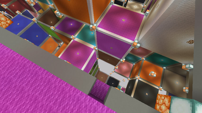
Suppose you’re making a game full of cubes in a voxel grid. To start, you simply render every cube with twelve triangles, two for each face. Helpfully, the GPU discards triangles that are facing away from the camera.
vistri=facingCamera \text{vis}_{\text{tri}} = \text{facingCamera}
Many faces are invisible because of an adjacent cube, so you stop rendering them.
vistri=neighborIsNotSolid∧facingCamera \text{vis}_{\text{tri}} = \text{neighborIsNotSolid} \land \text{facingCamera}
Drawing triangles individually is slow, so combine all the visible triangles in a 16×16×16 16 \times 16 \times 16 section into a buffer and render them together as a single mesh. To start, all sections are…
Background #
Suppose you’re making a game full of cubes in a voxel grid. To start, you simply render every cube with twelve triangles, two for each face. Helpfully, the GPU discards triangles that are facing away from the camera.
vistri=facingCamera \text{vis}_{\text{tri}} = \text{facingCamera}
Many faces are invisible because of an adjacent cube, so you stop rendering them.
vistri=neighborIsNotSolid∧facingCamera \text{vis}_{\text{tri}} = \text{neighborIsNotSolid} \land \text{facingCamera}
Drawing triangles individually is slow, so combine all the visible triangles in a 16×16×16 16 \times 16 \times 16 section into a buffer and render them together as a single mesh. To start, all sections are rendered.
vissection=true \text{vis}_{\text{section}} = \text{true}
Rendering sections that aren’t visible to the camera is expensive, so you use a 3D math library to check if each section intersects with the camera’s view frustum.
vissection=inFrustum \text{vis}_{\text{section}} = \text{inFrustum}
This basic level of occlusion culling is enough for many games! If objects are drawn mostly front-to-back, the depth buffer helps skip the expensive per-pixel texture lookups and shading steps for any hidden geometry. Still, drawing all those hidden sections is wasteful, and voxel games often have caves and tunnels just beneath the surface.
Advanced Cave Culling #
Minecraft’s culling was in this basic state before the introduction of Tommo’s Advanced Cave Culling Algorithm in 2014. That algorithm makes a few observations:
- Sections are rarely simply solid or empty. For example, many sections are filled with solid dirt on the bottom but open on the top. Computing connectivity between pairs of faces is useful information for tracing paths that rays can follow from an entry face to an exit face.
- Traversing sections with a breadth-first search starting from the camera visits sections approximately in order of their distance from the camera.
- Only following paths moving away from the camera that are allowed based on the connectivity graph culls many sections.
The math for any quadrant in 2D or octant in 3D is the same after reflection, so we shift the viewer’s section to the origin, and only consider the positive quadrant or octant, that is, the portion facing +x/+y or +x/+y/+z. The coordinates x, y, and z are integer section offsets from the viewer’s section position, and typically range from 0 to 32.
connected(x1,y1,x2,y2)=(x2,y2)∈outgoingForIncoming(x1,y1)visible(x,y)=reachable(x,y)∧inFrustum(x,y)reachable(0,0)=truereachable(x,y)=(reachable(x−1,y)∧connected(x−1,y,x,y))∨(reachable(x,y−1)∧connected(x,y−1,x,y)) \begin{align*} \text{connected}(x_1,&y_1,x_2,y_2) = (x_2,y_2) \in \text{outgoingForIncoming}(x_1,y_1) \ \text{visible}(x,y) &= \text{reachable}(x,y) \land \text{inFrustum}(x,y) \ \text{reachable}(0,0) &= \text{true} \ \text{reachable}(x,y) &= (\text{reachable}(x-1,y) \land \text{connected}(x-1,y,x,y)) \ & \quad \lor (\text{reachable}(x,y-1) \land \text{connected}(x,y-1,x,y)) \end{align*}
During the search, the directions for incoming paths to each section are recorded. This is used by outgoingForIncoming\text{outgoingForIncoming} to look up paths that can leave a section after entering through specific faces.
The only notable change in 3D is adding an axis to the traversal.
reachable(0,0,0)=truereachable(x,y,z)=(reachable(x−1,y,z)∧connected(x−1,y,z,x,y,z))∨(reachable(x,y−1,z)∧connected(x,y−1,z,x,y,z))∨(reachable(x,y,z−1)∧connected(x,y,z−1,x,y,z)) \begin{align*} \text{reachable}(0,0,0) &= \text{true} \ \text{reachable}(x,y,z) &= (\text{reachable}(x-1,y,z) \land \text{connected}(x-1,y,z,x,y,z)) \ \quad \lor &(\text{reachable}(x,y-1,z) \land \text{connected}(x,y-1,z,x,y,z)) \ \quad \lor &(\text{reachable}(x,y,z-1) \land \text{connected}(x,y,z-1,x,y,z)) \ \end{align*}
The breadth-first search to compute reachable\text{reachable} for each section only steps along two directions in 2D and three directions in 3D. The search initializes every section to unreachable. As it visits a section and considers its visible neighbors, that neighbor’s reachability and incoming face directions are updated.
This is fast and culls some invisible sections, but it’s very vulnerable to the “Ravine Problem”: the search can follow strange hooked paths across the terrain, down a hole, and into a cave, which rays of light could never follow.
Douira created a very fast angle-based refinement for the Minecraft optimization mod Sodium. If the incoming angle to a face is shallow enough, it can’t possibly traverse to the opposite face. This culls another ~11% of sections by forbidding many impossible paths.
This interactive grid demonstrates the ravine problem. The viewer is represented by a yellow light at the top left lighting visible sections. Click and drag to set or clear cells.
Frustum Clamping #
Tommo hints at further improvements at the end of his post with a frustum clamping prototype, but I believe it never made it into production in Java.
Frustums in 2D are simple: an origin point and two lines. 3D frustums are truncated pyramids with six planes defining the sides. If you simulate a frustum being clamped or clipped during a traversal, you either accumulate a large number of frustums that can see each cell, or have to do frustum merging when a cell has multiple paths to reach it. Both are potentially very expensive! Doing complex calculations for every section visited inflates frame times too much, and presumably prevented deployment.
Merging 2D frustums can be done by intersecting the largest frustum possible for a section with the unions of the incoming frustums. With angle intervals, unions and intersections are computed using min\text{min} and max\text{max} . These are approximations since the union can include angles in neither operand, but any overestimates merely render too much.
[a,b]∪[c,d]=[min(a,c),max(b, d)][a,b]∩[c,d]=[max(a,c),min(b, d)] \begin{align*} [a, b] \cup [c, d] &= [\text{min}(a, c), \text{max(b, d)}] \ [a, b] \cap [c, d] &= [\text{max}(a, c), \text{min(b, d)}] \end{align*}
When adapted for BFS and merging on quadrants, the math becomes:
reachable(x,y)=(reachable(x−1,y)∧connected(x−1,y,x,y)∧allowedByAngle(x−1,y,x,y))∨…minAngle(0,0)=0∘maxAngle(0,0)=90∘angle(x,y)=max(0,min(90∘,atan2(y,x))minAngle(x,y)=max(min(minIncoming(x,y)),angle(x+1,y−1))maxAngle(x,y)=min(max(maxIncoming(x,y)),angle(x−1,y+1))allowedByAngle(x1,y1,x2,y2)=max(minAngle(x1,y1),angle(x2+1,y2−1))<min(maxAngle(x1,y1),angle(x2−1,y2+1)) \begin{align*} \text{reachable}(x,y) &= (\text{reachable}(x-1,y) \land \text{connected}(x-1,y,x,y) \ & \quad \land \text{allowedByAngle}(x-1, y, x, y)) \lor \dots \ \text{minAngle}(0,0) &= 0^\circ \ \text{maxAngle}(0,0) &= 90^\circ \ \text{angle}(x,y) &= \text{max}(0, \text{min}(90^\circ, \operatorname{atan2}(y,x)) \ \text{minAngle}(x,y) &= \max(\min(\text{minIncoming}(x,y)), \text{angle}(x+1,y-1)) \ \text{maxAngle}(x,y) &= \min(\max(\text{maxIncoming}(x,y)), \text{angle}(x-1,y+1)) \ \text{allowedByAngle}&(x_1,y_1,x_2,y_2) = \ &\max(\text{minAngle}(x_1,y_1), \text{angle}(x_2+1,y_2-1)) \ \quad < &\min(\text{maxAngle}(x_1,y_1), \text{angle}(x_2-1,y_2+1)) \end{align*}
minIncoming\text{minIncoming} and maxIncoming\text{maxIncoming} are the sets of minAngle\text{minAngle} and maxAngle\text{maxAngle} values from all neighboring sections that can reach the current section.
It’s easier to understand graphically. Hovering shows the view frustums for a cell. The red shading represents the unobstructed permitted angles, and blue shows what has been computed by the BFS. Note how the cells at (0, 1), (1, 0), and (1, 1) all have identical permitted angles, because visibility is computed for a viewer anywhere inside a section. This is handled by calculating the minimum and maximum angles between different corners of the section in allowedByAngle\text{allowedByAngle} .
This 2D frustum clamping using allowed angle ranges is quite simple. In 3D, we could work out how to do similar unions and intersections with frustum planes, but the math is quite complex. Instead, we can track the allowed angles independently for three planes (XY, XZ, YZ) and ensure that the angle restrictions permit the traversal in each of the three planes during the search.
Fast Frustum Clamping #
Computing arctangent for every cell is extremely expensive. We can avoid this by simplifying the math. The code is doing intersections and unions over angle intervals, but it doesn’t care about the precise values of the angles, just their relative orderings. Storing yx \frac{y}{x} works, but even division might be too expensive. The rise and run of the slopes can be stored instead. When comparing slopes, divisions are unnecessary:
y1x1<y2x2y1x1⋅x1⋅x2<y2x2⋅x1⋅x2y1⋅x2<y2⋅x1 \begin{align*} \frac{y_1}{x_1} &< \frac{y_2}{x_2} \ \frac{y_1}{x_1} \cdot x_1 \cdot x_2 &< \frac{y_2}{x_2} \cdot x_1 \cdot x_2 \ y_1 \cdot x_2 &< y_2 \cdot x_1 \end{align*}
Unfortunately, both of these representations of slopes can still be too slow, especially in Java where SIMD is mostly inaccessible. Across the three planes, computing allowedByAngleallowedByAngle with slopes requires 30 multiplies and 12 min/max operations.
To make it even faster, we can switch to precomputed lookup tables. This angle code has already been computing visibility from an entire source section, not for a specific viewer, so there are not many relative section offsets to compute arctangents for. Minecraft’s maximum chunk distance is 32, so a table storing precomputed arctangent values for x,y∈[0,31]x, y \in [0, 31] works well. The LUT stores the minimum and maximum angles for a given section offset as a 20-bit value, packed into 4KiB that easily fits in L1 cache.
One LUT lookup per plane lets us build a 60-bit number representing all permitted min/max angles. Some magic bitwise operations make it possible to do branchless compare and selection operations over the six quantized values, reducing the allowedByAngle computation to simple arithmetic and a few well-predicted branches.
This method returns the result of allowedByAngle\text{allowedByAngle} for a neighbor and also updates the BFS state for the given section.
boolean intersectAngles(SectionPos origin, RenderSection other, int frame) {
var dx = Math.abs(origin.getX() - this.getChunkX());
var dy = Math.abs(origin.getY() - this.getChunkY());
var dz = Math.abs(origin.getZ() - this.getChunkZ());

while ((dx | dy | dz) >= 32) {
// Compress coordinates to fit within the [0, 31] LUT range.
// This causes slight precision loss for the farthest sections.
dx >>= 1; dy >>= 1; dz >>= 1;
}

long baseAngles = ANGLE_LUT[dx + (dy << LUT_SHIFT)] |
((long) ANGLE_LUT[dz + (dx << LUT_SHIFT)] << (2 * ANGLE_BITS)) |
((long) ANGLE_LUT[dy + (dz << LUT_SHIFT)] << (4 * ANGLE_BITS));

long pathAngles = angles_max_min(other.allowedAngles, baseAngles);

// Check if max < min for any plane, which means the path is occluded.
if (angles_less_than(
(pathAngles & ANGLES_MAX_MASK) >> ANGLE_BITS,
pathAngles & ANGLES_MIN_MASK) != 0) {
return false;
}

if (this.lastVisibleFrame == frame) {
// This section has been visited before on *this frame*.
// Union the angles: [min(oldMin, newMin), max(oldMax, newMax)]
pathAngles = angles_min_max(pathAngles, this.allowedAngles);
}
this.allowedAngles = pathAngles;
return true;
}
Is this fast enough? Maybe! On my computer it adds 60ns to each BFS step (0.5ms total for 8000 sections) in exchange for culling an additional 5-25% of sections. Deciding to spend CPU to save GPU depends on which is presenting a bottleneck. Even when it’s too expensive to run every frame, the results are valid for a viewer anywhere inside the section, so it can be computed once per section.
Demo #
Interact with all the algorithms discussed here, including changing the quantization precision or the light size.
3D #
Here’s a demonstration of the shadowing in 3D with rudimentary controls. The boundaries between lit and unlit air cells are shown as columns of light.
Thanks to the Sodium development team for feedback on code and this blog post.
Notes #
Representing the allowed angles as a bitset, where a set bit 0 means angles in [0,5∘][0, 5^\circ] are allowed, has too much precision loss to be useful, despite how attractive making union and intersection bitwise OR and AND are.
Minecraft 1.21.10 has a bug in its occlusion culling that makes it have false positive occlusions and renders holes in the world. Sodium doesn’t! This is easy to reproduce by creating an occlusion torture test, where each 16×16×16 16 \times 16 \times 16 section has random faces made solid.
This algorithm should be possible to extend to voxel octrees.
Related Work #
Is this novel? Would consulting previous work first have saved a lot of time? Maybe! Occlusion culling using voxels has been extensively researched, but I couldn’t find a description of this particular method anywhere. Modern voxel algorithms are largely focused on GPU-driven rendering and occlusion culling, so CPU methods are less popular.
The most similar algorithm is described in “Conservative Volumetric Visibility with Occluder Fusion” by Schaufler et al., which finds blockers that can occlude voxels and similarly extends to 3D by tracking each plane separately. However, it tracks the blockers individually, making fixed-overhead BFS impossible, and presumably requires more complex math. Fast Frustum Clamping can be viewed as a descendant of this paper, but the perspectives are reversed. Occlusion culling algorithms can answer two opposing questions: is this definitely invisible, or is this maybe visible? Traversing through a scene graph to visit all probably-visible sections is often simpler than the alternative of traversing to mark the occluded sections!
Umbra 3D, which has been integrated into Unity and many other game engines, uses a voxel scene representation to create a graph of cells and the portals between them without requiring manual placements.