May 2025 (First Draft) - October 2025 (Final)
![]()
Last month, Bill Gates celebrated the 50th anniversary of Microsoft by releasing its earliest known source code: the Altair BASIC interpreter 3.0. The significance of Microsoft’s first endeavor has been discussed ad nauseum by industry and insiders for decades - to which, I have nothing to add.
As for the source code, I hope to help future code readers enjoy exploring minds from an earlier era. The first hurdle? Converting the 314 pages of fanfold impact printouts into something easier to analyze. Here you go:
Altair BASIC 3.0 source on [GitHub]…
May 2025 (First Draft) - October 2025 (Final)
![]()
Last month, Bill Gates celebrated the 50th anniversary of Microsoft by releasing its earliest known source code: the Altair BASIC interpreter 3.0. The significance of Microsoft’s first endeavor has been discussed ad nauseum by industry and insiders for decades - to which, I have nothing to add.
As for the source code, I hope to help future code readers enjoy exploring minds from an earlier era. The first hurdle? Converting the 314 pages of fanfold impact printouts into something easier to analyze. Here you go:
Altair BASIC 3.0 source on GitHub:
- WYSIWYG from the paper feed (repo / raw)
- Assembly only (with and without line numbers)
- ...and more view slices discussed in the repo
Armed with accessible source, we’re ready to start the journey to appreciate what Gates called “the coolest code I’ve ever written”.
My Goal: To break knowledge barriers preventing modern programmmers from jumping in to the code by collecting foundational knowledge in one place (right here!)
Solid Foundations - Prerequisite knowledge for Altair BASIC
Computing in 1975 was more simple than today. It was possible for a young person to grasp the entire computation chain: from hardware and machine instructions through the single running program to the display / teleprinter. Much like three talented 20-somethings that shoehorned this BASIC interpreter in to 4K of memory. Simple ... but obscure by today’s standards.
We’ll walk through the tools of the era in rough order of importance. These tools are essential to understand exactly what we’re seeing in the source code without constant cross-referencing to ask “What is this?”. As we move down the list, the resources will address the broad implications of “Why” rather than “What or How”.
The Intel 8080 CPU
Key Resource:[The 8080 Assembly Language Programming Manual (1975)](https://maizure.org/projects/decoded-altair-basic/.\Intel-8080 Programmers Manual.pdf)
All assembly for Altair BASIC targets the Intel 8080. It’s on the programmer to bootstrap this chip to support their application. If you’re coming from an x86 background (like me), then you have to retrain your thinking since this processcor predates the 8086 by four years. The architecture at the time was known as MCS-80, and had several quirks were eventually ironed out. The most important points for our purposes are:
The Registers
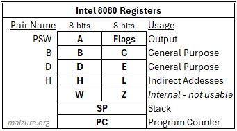
General purpose registers are 8-bits wide. The register names do not follow later conventions leading to software compatibility complications with later x86 CPUs. Fortunately, the convention isn’t too far from what the 8080 provides.
Register Pairs The 8080 implements ‘register pairs’ for performing 16-bit computations using two 8-bit registers. This idea falls away with the more generalized x86 architecture after 1978. The key point for the Altair BASIC source is to know the pairs, how to reference them, and the 8 specific instructions involving pairs. In general, instructions reference the given register unless it is a special pair instruction.
For example, the INX B instruction will increment the combined B,C value by one. In most cases this means ‘INX B’ will actually only increment the value in C unless it is all 1s, which carries in to B. The special instructions to watch for are:
| Instruction | Valid Regs | Purpose |
|---|---|---|
| PUSH | B,D,H,PSW | Adds the two-byte contents of the register pair to the stack |
| POP | B,D,H,PSW | Fills the register pair with two bytes from the stack |
| DAD | B,D,H,SP | 16-bit add of the register pair and H,L contents. DAD H is equivalent to left shift of H,L |
| INX | B,D,H,SP | 16-bit increment of the target register pair |
| DCX | B,D,H,SP | 16-bit decrement of the target register pair |
| XCHG | None | Swaps H,L with D,E |
| XTHL | None | Swaps H,L with *SP+1,*SP respectively |
| SPHL | None | Moves the contents of H,L in to SP directly (no memory changes) |
Interrupt Vectors The first 64 words in memory (0o0000-0o0100) are dedicated to handling interrupts. External devices invokve interrupts by supplying an RST instruction with a handler address. The processor expects the application programmer to lay out eight routines of 8 bytes each from at the start of memory. If the application does not use hardware interrupts then should be disabled on initialization with a ‘DI’ instruction. Refer to Chapter 5, Page 60 of the 8080 guide for the details.
Altair BASIC disables all hardware interrupts and instead uses the handlers to dispatch common functions. The CPU still responds to RST invoked from within the application, but will not listen for hardware RSTs. Discussion about the Altair BASIC handlers continues below
The MACRO-10 Assembler
Key Resource: The MACRO Assembler Reference Manual (1973 and 1978*)
Altair BASIC was written on Harvard’s PDP-10 and tested on an 8080 emulator written by Paul Allen. Consequently, Gates and Allen used the MACRO-10 assembler and its extended features. You’ll need to recognize these features in order to quickly read through the code.
*The 1978 reference didn’t exist when Altair BASIC was developed, but I find the quality easier to read than the earlier manual.
Pseudo-Ops Instructions provided by MACRO-10 range from crafting specific bytes and sequences to merely visual styling of the source listing when printed. For Altair BASIC, know these operations:
| Pseudo-Op | Count | Purpose |
|---|---|---|
| BLOCK | 49 | Reserves memory space. No code generated. Next instruction address skips by BLOCK size |
| DEFINE | 29 | Creates a symbol as a macro of other symbols. Similar to #define in C |
| END | 2 | Mandatory last statement in a MACRO program |
| EXTERNAL | 16 | Reserves symbols for resolution at load time. Cannot be defined in current source |
| IFE | 205 | Conditional branching assembly - see below for further discussion |
| IFN | 351 | Conditional branching assembly - see below for further discussion |
| INTERNAL | 27 | Tags symbol as global to all other loaded programs. Must be defined in this source |
| LIST | 2 | Resumes listing the program following an XLIST statement |
| PAGE | 48 | Ends the logical page of source. Only relevant for source display |
| PRINTX | 21 | Outputs text during assembly |
| RADIX | 3 | Sets the radix (base) in the program and is applied to all numbers |
| RELOC | 8 | Directly sets the address of the next (and subsequent) instructions |
| SALL | 2 | Suppresses all macros and expansions. Helpful when listing sources |
| SEARCH | 2 | Declares a source for MACRO-10 to search for unresolved symbols |
| SUBTTL | 50 | Sets the subtitle see at the top of source listing pages |
| TITLE | 2 | Sets the title of the program |
| XLIST | 2 | Suspends output of the program listing during Pass 2 |
| XWD | 53 | Generates code specified. Useful for crafting exact instructions. See below |
Conditional Assembly IFE and IFN evaluate expressions follow the branch that evaluates to 0 or not 0 respectively. The source makes extensive use of IFE and IFN pseudo-ops to generate only the code necessary for the build target. The target is chosen with pre-configured with constant values in a ‘Common File’ prior to assembly. The assembler determines which code paths are dead and only generates output on the desired path based on evaluation of the given expression. The source includes all possible code paths, but only one specific path is built based on the configuration.
Here is a sneak peak of the ‘Common File’ from the first page of source showing IFE in action. We will discuss how to read this properly in coming sections. Bolded comments are mine:
BASIC MCS 8080  GATES/ALLEN/DAVIDOFF    MACRO 47(113) 03:12 10-SEP-75 PAGE 1
C        6-SEP-64 03:11         COMMON FILE

1                                  00100   SEARCH  MCS808
2                                  00200   SUBTTL  COMMON FILE
3                                  00300   SALL
4                  000002          00400   LENGTH==2            /* LENGTH of 2 implies 12K (Extended) BASIC build target */
5                  000001          00500   REALIO==1            /* REALIO of 1 means real machine, not simulator */
6                  000000          00600   CASSW==0             /* The 000000 to the left shows generated constant */
7                  000000          00700   PURE==0
8                  000000          00800   LPTSW==0
9                  000000          00900   DSKFUN==0
10                  000000          01000   CONSSW==0
11
12                  000016          01200   CLMWID==^D14
13                  000000          01300   RAMBOT=^O20000
14                  000001          01400   CONTRW==1
15                                  01500   IFE     REALIO,<     /* IFE expects a 0 but gets a 1 -- branch not taken */
16    /* Nothing generated          01600           LPTSW==0
17     *                            01700           CASSW==0
18     *                            01800           CONSSW==0
19     *                            01900           DSKFUN==0
20     *                            02000           CONTRW==0>
21     *
22     *                            02200   IFE     LENGTH,<     /* IFE expects a 0 but gets a 2 -- branch not taken */
23     *                            02300           EXTFNC==0    /* These are the settings for 4K BASIC */
24     *                            02400           MULDIM==0
25     *                            02500           STRING==0
26     *                            02600           CASSW==0
27     *                            02700           LPTSW==0
28     *                            02800           DSKFUN==0
29     *                            02900           CONSSW==0
30     *                            03000           CONTRW==0>
31     *
32     *                            03200   IFE     LENGTH-1,<   /* IFE expects a 0 but gets a 1 -- branch not taken */
33     *                            03300           EXTFUN==1    /* These are the settings for 8K BASIC */
34     *                            03400           MULDIM==1
35     */                           03500           STRING==1>
36
37                                  03700   IFE     LENGTH-2,<   /* IFE gets a 0 -- branch taken and constants output */
38                  000001          03800           EXTFUN==1    /* These are the settings for Extended BASIC */
39                  000001          03900           MULDIM==1
40                  000001          04000           STRING==1>
Other Small Details
- OCTAL format is used for nearly all addresses throughout the source. Couting is 1-7, 10-17, 77 + 1 = 100, etc.
- Symbols have a maximum of 6 characters. This includes jump lables and variables
- Some symbols and functions are not resolved with the source, such as ADR and DC. These are likely in MCS808 shown on line 1
- Many pseudo-ops are dedicated to clean code display and not code generation, like TITLE, PAGE, SALL, etc
- The XWD pseudo-op is used in unexpected ways to shorten code generation. More on that later.
The basics of BASIC
Key Resource: [MITS BASIC Manual (1975)](https://maizure.org/projects/decoded-altair-basic/.\AltairBASIC Manual 75.pdf)
The design and operation of BASIC interpreters were well-known in 1975. Dartmouth BASIC had been widely shared for over 10 years and universities included interpreter implementation in computer science curricula. This allowed Gates and Allen to focus on the immediate challenge of implementing BASIC on the resource-constrained Altair.
For us, it’s helpful to understand what a generic BASIC intepreter does beforehand so we can focus on the Altair implementation and appreciate the optimizations made it feasible on limited hardware. The BASIC manual linked above tells us how the software should behave and provides many hints about the implementation.
The user view of the runtime experience:

Even in 1975, interactions and outputs feel similar to a modern Python interpreter. Users input single immediate (direct) command, such as PRINT 2+2, and expect an immediate response. Alternatively, a user may enter a long program of (indirect) commands, and the computer will proceed accordingly with potentially interactive outputs. An interpreter facilitates this experience by reading input, checking for validity, evaluating requests, providing output, and preparing for the next commands.
Altair BASIC compresses this process as much as possible in order to operate with minimum memory space. There isn’t enough resources to support generalized semantic analysis as the output will happen in a single pass. Under the hood, the solution looks like this:

The names in [square brackets] are the symbol names of the supporting data structures used in Altair BASIC. We will delve in to the data structures during the loading discussion and step through this loop during the execution discussion.
The Altair 8800
Key Resource: [Altair 8800 Operator’s Manual](https://maizure.org/projects/decoded-altair-basic/.\Altair 8800 Operators Manual.pdf) Optional Resource: [Altair 8800 Theory of Operations and Schematics](https://maizure.org/projects/decoded-altair-basic/.\Altair 8800 Theory Of Operations and Schematics Manual.pdf)
Ironically, the Altair itself is last on the list of things to know for the BASIC source code. We can talk all day about the box itself – it’s the entire reason we’re here! But for our purposes, BASIC talks to the 8080 while it lives in the memory supplied by the Altair. The challenges of manipulating the front panel and configuring peripherals (teletypes, tapereaders, etc) are assumed to be overcome by the time BASIC loads. Considering that the mythology says Gates and Allen didn’t even have a physical Altair to build and test BASIC on, we can also get by without digging in too far. Feel free to dig in to the manuals, but the most important points for us are:
-
Three memory configurations: 4K, 8K, and Extended (12K or more)
-
Altair uses a two-stage loading process to start BASIC (Details on page 46 of the BASIC manual)
-
First stage loader begins to read from an external source (tape, cassette, etc)
-
Second stage loader verifies that BASIC was loaded correctly and begins execution
-
This was the loader that legends say Allen wrote while the plane landed for the product demo
-
Altair begins executing at memory location 0, which is where we begin the journey into the BASIC source
The Source Code
Here are facts about the source released by Bill Gates in April 2025:
-
Source version states that it is Altair BASIC 3.0
-
314 pages of fanfold paper scanned in to 157 pages of PDF (2 physical pages per PDF page)
-
One physical page is 11“ x 14“ 7/8
-
66 lines per page (6 LPI) with 132 characters per line. From the top:
-
2 unused lines
-
2 header lines
-
1 blank line
-
53 source content lines
-
8 blank footer lines
-
Source is two files combined (F3 and F4) which includes the common (config) file for each prepended
-
F3 printout is dated 10 September 1975
-
F4 printout is dated 27 August 1975
-
12,628 lines of source, including comment lines and whitespace
-
F3 contains 7801 lines of source including its common file.
-
F4 contains 4827 lines of source including its common file.
-
F3 includes the core BASIC intepreter
-
F4 contains the math package and the system initalization code
-
System initialization code is the last section loaded, runs once, and the space is recovered as program memory area
-
Symbol tables from the assemblers first-pass(?) are appended to the source listing after both F3 and F4
Layout of the source release
The source printouts contain several sections of note, which are duplicated between source files F3 and F4.
 F3/F4 Headers - Identifies the subsequent file along with process, print job, and system information
Common File - An ‘included’ configuration file with static variables for assembler usage. Note that F3 and F4 are using different Common File configurations (12K and 8K respectively).
F3/F4 Source - The program! F3 is BASIC, F4 is Math package and system initialization
F3/F4 Trailer - Verification of print job process complete
Duplicated Pages - Extra pages of F3 snuck in to F4. Physically the same page, but printed and scanned separately
F3/F4 Symbol Table - The list of symbols known to the respective source file. Includes a value,reference and a possible flag such as
F3/F4 Headers - Identifies the subsequent file along with process, print job, and system information
Common File - An ‘included’ configuration file with static variables for assembler usage. Note that F3 and F4 are using different Common File configurations (12K and 8K respectively).
F3/F4 Source - The program! F3 is BASIC, F4 is Math package and system initialization
F3/F4 Trailer - Verification of print job process complete
Duplicated Pages - Extra pages of F3 snuck in to F4. Physically the same page, but printed and scanned separately
F3/F4 Symbol Table - The list of symbols known to the respective source file. Includes a value,reference and a possible flag such as ext or spd. See the 1978 MACRO book page 6-4 for flag details.
F3/F4 Cross-Reference Symbol Table - The CR Symbol Table shows a list of line numbers for each symbols. Line number is the assembler assigned number on the far left of a page, not programmer provided number. See section 2 below.
Source subsections
The F3 and F4 source files group their routines in to subsections, each titled conveniently at the top of each page. The sections are:
| F3 Sections (BASIC Interpreter) | F4 Sections (Math Package) |
|---|---|
| Common File | Common File |
| Version 3.0 | Math Package Configuration |
| Some Explanation | FP Addition and Subtraction |
| RST Routines | Natural Log Function |
| Dispatch Tables,Reserved Words, Error Text | FP Multiplication and Division |
| Low Segment - RAM | Sign, SGN, Float, Neg, ABS |
| Text Contants | FP Movement Routines |
| General Storage Management | Compare Two Numbers |
| Error Handler, Ready, Compacting, New, Clear, Main | Integer, Single, and Double Conversion |
| The LIST Command | Greatest Integer Function |
| FOR Statement | Integer Arithmetic Routines |
| New Statement Fetcher | Double Precision Arithmetic |
| Restore, Stop, End, LINGET, CHRCON | FP Input Routines |
| Run, Goto, Gosub, Return | FP Output Routines |
| Let | Exponentiation and Square Root |
| On Goto | Exponential Function |
| If ... Then | Polynomial Eval and Random Numbers |
| Sine, Cosine, and Tangent | |
| Input and Read | Arctangent |
| Next | System Initialization |
| Formula Evaluation | |
| Dimension and Variable Searching | |
| Multiple Dimension | |
| Function and Integer to Float Routines | |
| Simple User-Defined-Functions | |
| String Functions | |
| Fancy List, Delete, Edit, LLIST | |
| Disk Code | |
| CLOAD, CSAVE, Console | |
| Peek and Poke |
Anatomy of a source page
The source listing from the MACRO assembler includes both the source and generated machine code for the specific platform configured in the common file. I will predominantly focus on the source code on the right hand side of the page. People interested in direct platform code might be interested in following the left-hand side, which is helpful as a check for assembler operation.
Here is an annotated view of a typical page of the source:

Section 2 line numbers are relevant for the source listing only. Sections 3,4 and 5 are the generated output of the assembler. Sections 6 and 7 are the input assembly code
| Section | Purpose |
|---|---|
| 1 | The two-line header at the top of every source page. Important info includes the page, file, and section subtitle |
| 2 | The listing line number. This is only relevant for the printout and isn’t a part of the source |
| 3 | The address of the subsequent two words of generated bytes. Ususally sequential unless explicitly skipped (i.e BLOCK statement) |
| 4 | Upper 18-bit word of output. Not directly applicable for the 8080 which has at most 16-bits addressable. Throughout the source code, only 3 values are observed. 001000 whenever the lower byte is a instruction (op-code). 000000 when the lower byte is an operand (data). And 777777 for negative immediate values. |
| 5 | Lower 18-bit word of output. Contains the relevant generated code for each opcode or operand. |
| 6 | Source line number. These were explicitly written by Gates et al during development. |
| 7 | The hand crafted MACRO-10 and MCS-80 assembly code and comments. |
Key points:
- Only addresses appearing in Section 3 are live code paths that appear in the output build. The address is the location in the output. This is controlled by the configuration files
- When sections 3 and 4 are blank yet section 5 has a value: This indicates a constant value referenced by the assembly during a pass
- Values in section 5 with a trailing apostraphe indicate a relocatable memory reference, otherwise treat it as a value (opcode or operand)
Code quirks and idioms
Combine fifty year-old code with resource-constrained hacks and you’ll have a code base littered with headscratchers. I’ll dissect some ideas to watch for as we walk through the source.
XWD pseudo-op used for flow control The XWD pseudo-op provided by the MACRO-10 assembler is typically used to craft bit-level specific output without interference from the assembler. Quite literally “Insert only this value at the current address”. Microsoft used XWD to change control flow by inserting instructions that force subsequent lines to be read as operands (data) rather than executing them. A few examples:
1874  002072' 001000  000036          27940   SNERR:  MVI     E,ERRSN         ;"SYNTAX ERROR"
1875  002073' 000000  000002
1876  002074' 001000  000001          27960           XWD     ^O1000,1        ;"LXI B," OVER THE NEXT 2
1877  002075' 001000  000036          27980   DV0ERR: MVI     E,ERRDV0        ;DIVISION BY ZERO
1878  002076' 000000  000013
1879                                  28000   IFN     LENGTH,<
1880  002077' 001000  000001          28020           XWD     ^O1000,1        ;SKIP NEXT TWO
1881  002100' 001000  000036          28040   NFERR:  MVI     E,ERRNF>        ;"NEXT WITHOUT FOR" ERROR
1882  002101' 000000  000001
1883  002102' 001000  000315          28060   ERROR:  CALL    STKINI          ;RESET THE STACK AND FLAGS
This code segment has multiple entry points on lines 1874, 1877, and 1881 that set different string references but all ‘fall through’ to line 1883 without side effects. The trick is that the XWD instructions place an ‘LXI B’ op-code only without adding the 16-bit immediate operand expected causing the MVI instruction and its operand to be loaded into register pair BC. If we entered this code block at the top from like 1874, the “syntax error” string reference is loaded in to E, then the XWD instruction is executed as LXI B, gobbling up the subsequent MVI and it’s operand as data rather than executing them. This repeats on line 1880 and thus we fall through to line 1883.
So why not just use a real LXI B, or even a jump to ERROR? It’s more memory expensive – the assembler will use 3 bytes to fill out LXI and its operands or jump reference. Using XWD only sacrifices 1 byte and smashes BC while weaving 3 code paths that slide to the same exit point without consequential side effects.
Another XWD example:
2372  002646' 001000  000361          34640   FOUND:  POP     PSW             ;TAKE OFF GARBAGE ORIG POINTER
2373  002647' 001000  000170          34660           MOV     A,8             ;GET RESERVED WORD #
2374  002650' 001000  000366          34680           ORI     128             ;SET MSB TO FLAG AS RESERVED WORD
2375  002651' 000000  000200
2376  002652' 001000  000362          34700           XWD     ^O1000,^O362    ;"JP" AROUND THE POP H AND MOV A,M
2377  002653' 001000  000341          34720   TABEND: POP     H               ;GET BACK ORIG POINTER
2378  002654' 001000  000176          34740           MOV     A,M             ;GET BACK ORIG CHAR
2379  002655' 001000  000321          34760           POP     D               ;GET STUFF POINTER BACK
This produces the same effect of skipping 2 instructions without smashing BC in the process. But why use JP (Jump If Positive)? The previous instruction of ORI 0b10000000, in addition to it’s BASIC use for signalling a reserved also, also guarantees that the SIGN flag will be reset (negative), thus the fake JP branch will never be taken and we will fall through, saving us 2 bytes while preserving key registers.
Therein lies the art of weaving together multiple code paths and choosing the most appropriate operation to subtitute based on how many instructions you need to skip while avoiding destructive side effects like smashing important registers. Here is a summary of XWD usage throughout the Altair BASIC source:
| XWD Instruction | Mimicks | Desired effect | Side effects |
|---|---|---|---|
| XWD ^O1000,1 | LXI B | Skips 2 instructions | Smashes register pair BC |
| XWD ^O1000,^O16 | MVI C | Skips 1 instruction | Smashes register C |
| XWD ^O1000,^O21 | LXI D | Skips 2 instructions | Smashes register pair DE |
| XWD ^O1000,^O76 | MVI A | Skips 1 instruction | Smashes accumulator |
| XWD ^O1000,^O362 | JP | Skips 2 instructions | No side effects |
| XWD ^O1000,^O366 | ORI | Ensure register A isn’t zero, Z flag is reset, skips 1 instruction | Smashes A, Z flag reset |
CPI instruction as a fast ‘type’ mechanism
The source often uses the CPI instruction to make a fast determination about an input value. The most common situation is comparing a value in the accumulator for an exact value. If the values match, the ZERO flag will be 1 and the subsequent branch will usually follow a JZ, JNZ, CZ, or CNZ instruction.
In the case of user input, we see CPI often compared to “A”. If the user has input a digit (0-9) in to the accumulator, the “A” charcater will assert the Carry flag, while an input letter will not. This way we can quickly determine if the user input a number or letter as expected and branch using JC, JNC, CC, or CNC.
Note that this behavior is not consistent when characters arrive in the accumulator with the RST routine CHRGET, because it directly manipulates flags during the call.
Unresolved symbols
Not every symbol seen in the source has a definition that we can reference. I believe most of these are included in the universal file suggested by SEARCH MCS808 line that unfortunately I can’t find references to. It’s essentially an #include or ‘import’ statement. I’ve made some educated guesses about the meaning of these symbols, but I’m open to better interpretations if anyone has better information. Until then, consider these:
$CODE- Always resolves to 0 (zero) in this assembler pass. Likely the offset to the first address of code (code segment in x86 lingo) to generalize the load address.ADR(x)- Reserves the current two-bytes as an address to the given routine. Wrapped in a localADRPdefinition to include a precedence value for the operator table.DC- Define Constant. Used to allocate static string data to the current space in memory. Similar to the DB directive in x86. Altair BASIC wraps this withDCI,DCE, andDCLhelpers early in the assembly.VMOVE- Used to copy descriptors in the 12K version. This external routine prefers 3-byte descriptors vs the 4-byte internal design used by theMOVEroutine in 4K and 8K.
Number base ambiguity
By default, all addresses are read in octal format (base 8). All immediate values in operands are decimal (base 10). The following control delimiters tell the assembler how to explicitly handle the subsequent number:
^O- Octal number. So^O76is equal to decimal 62 and binary 00111110^D- Decimal number. So^D76is equal to octal 114 and binary 01001100^B- Binary number. Included here for completion, but this isn’t actually used in the code
You might wonder about hexadecimal? It turns out that MACRO in this era didn’t have a built-in hex notation. Word sizes in the mid 1970s hadn’t settled to be a multiple of 8/16, and the PDP-10 itself used 36-bit words (18-bit half-words), to which octal representation is better aligned. The PDP-8 was 12-bit words but the later PDP systems did ultimately land on 16-bit words.
The RET trampoline
The source code makes some use of return instructions not paired with a previous CALL instruction. Some address is pushed on to the stack, possibly much earlier, before the eventual RET invocation. If you see an unexplained return in the command sequence, but a jump brought you to this code block, the look to the nearest PUSH for further explanation.
In fact, be prepared for all forms of changing flow control such as calls, jumps, returns, and direct loading of the program counter with PCHL. It all happens in Altair BASIC.
Loading Altair BASIC
The memory footprint of a program was very easy to understand in the simple days of the 1970s. There is no OS, thus no virtual memory or paging system, and certainly nothing like ASLR. Altair BASIC owned the box and could directly address any physical space in memory. When the program tape read the final byte in to memory, execution is ready to begin from memory location 0.
Before running the program, we’ll review how it is laid out in memory, what the key sections are, why the program is organized in this way, and what structures support execution.
The view at load time
Altair BASIC lives in memory in the same order of memory addresses from section 3 of the source pages (example shown earlier). Here is the memory map of the program:

Starting from the interrupt handlers, the code drops down to fixed tables used for dispatch, then to static variable spaces. The 2nd half of the code is the runtime-execution, the largest sections being the BASIC statements and math package.
Altair BASIC follows the classic pattern of keeping single-use and optional-use code at the end so that this space can be recovered for dynamic storage. System initialization code runs once at the end, and the optional math functions follow before, allowing these final two blocks of ~730 bytes to be reclaimed at run time.
Interrupt vectors
We’ll dig in to some detail of the handlers now, including the purpose and specific code lines, but save the mechanical details and the extended handlers for the execution discussion
As mentioned earlier, the 8080 CPU architecture allows the first 64 bytes of memory to be used for interrupts: eight handlers with eight bytes each. There are caveats with the Altair BASIC implementation.
- The first instruction at memory location 0 is ‘DI’, which disables all hardware interrupts system-wide. Interrupts are never enabled again elsewhere in code. No external interrupts will ever invoke the handlers while Altair BASIC is running.
- Software interrupts from within AltairBASIC will still trigger jumps to the interrupt handlers via the RST instruction and macro’d friendly name
- AltairBASIC does not use the first or last handler and instead uses that space for initialization and user-defined functions
- Be aware of PC and stack composition in the handlers - not all use RET directly and some jump arbitrarily
- The discrepancy between the 64 actual bytes for handlers and the 67 bytes noted in the load time layout is due to the final unused routine overrunning its space without consequence
The interrupt handlers are dedicated to common low-level routines called often throughout the code. The RST instructions are MACRO’d to a friendly name. The eight handlers and their purposes are:
| Handler # | Offsets | Macro Name | Purpose |
|---|---|---|---|
| 0 | 0-7 | None | Not an interrupt handler. Jumps to init at the end of code, which self-modifies jump to “OK” |
| 1 | 10-17 | SYNCHK | Checks the character currently pointed at for a specific value, leading to possible syntax error |
| 2 | 20-27 | CHRGET | Increments to the next character and fetches it in to accumulator |
| 3 | 30-37 | OUTCHR | Outputs the value in the accumulator to the terminal |
| 4 | 40-47 | COMPAR | Compares the values of register pairs DE and HL with result in FLAGS. Carry = DE > HL, Zero means equal. |
| 5 | 50-57 | FSIGN | Checks the sign of the floating accumulator by setting the actual accumulator to the same sign |
| 6 | 60-67 | PUSHM | Pushes memory location at HL to the stack. Dereferneces value to BC |
| 7 | 70-103* | None | Not a handler, but can be set by the user for their own purpose. *This handler runs longer than designed |
Now for the lines of code that made up each handler location. I’ve removed original comments, whitespace, and machine code for clarity. I’ve added my own comments in bold that I believe may be relevant from the modern viewpoint, but I highly recommend reading the original comments in the source.
Interrupt 0 - Not used (memory location 0-7 octal)
13040   START:  DI            /* Disables external interrupts */
13060           JMP     INIT  /* Jumps to system init */
13080
13160   IFN     LENGTH-2,<    /* Excess space used for static
13180           ADR(DEINT)       pointers to routines */
13240           ADR(GIVABF)>
13260
13300   IFE     LENGTH-2,<
13320           ADR(FECINT)
13340           ADR(MAKINT)>
The first line of this handler is the first line for the whole program: Disable external interrupts, which are never reenabled. The next instruction jumps out of the handler to the system initialzation routine, which modifies this jump instruction to as a jump to ‘Ready’, which is effectively the top of the main loop. This way if the system ever somehow jumps back to insturction 0, it can pick up normal execution.
Interrupt 1 - SYNCHK (memory location 10-17 octal)
13600           MOV     A,M     /* Get next char from M in to A */
13620           XTHL            /* Swap HL and SP, SP+1
13640                                  M now looks at char to verify
13660           CMP     M       /* If they match, Z=1 */
13680
13700           INX     H       /* Manual advance to next instruction */
13720           XTHL            /* Restore to stack for eventual RET */
13740
13760           JNZ     SNERR   /* No match - error, else fall down to CHRGET */
SYNCHK verifies that the next input character matches the character given to the handler.
A successful SYNCHK will always execute the next handler (CHRGET) because execution falls through to pull the character in to A.
Interrupt 2 - CHRGET (memory location 20-27 octal)
14060   IFE     LENGTH,<CHRGTR:>  /* In 4K, we skip a later inline optimization */
14080           INX     H         /* Advance pointer to next character */
14100           MOV     A,M       /* Pull it in to A */
14120           CPI     ":"       /* A with ":". 0-9 force carry bit*/
14200   RNC                       /* If a letter, return to get more letters */
14220   JMP     CHRCON            /* Continue CHRGET later in source */
Loads the next input character in to A before passing execution to an extended routine, which skips spaces and handles numbers.
It’s worth discussing the CHRCON extended handler in this space because it has a subtle flag manipulation:
/* Only digits and control characters make it this far - letters returned already above */
43280   CHRCON: CPI     " "       /* Check for space, zero if true */
43300           JZ      CHRGTR    /* It's a zero - get another character */
43320           CPI     "0"       /* Digits will not have carry asserted at this point */
43360           CMC               /* Invert Carry - Digits will now have carry asserted */
43380           INR     A         /* Add one to reset flags */
43400           DCR     A         /* Subtract back to original so Zero means A=0 */
43420           RET
Interrupt 3 - OUTCHR (memory location 30-37 octal)
14360   OUTDO:  PUSH    PSW            /* Save FLAGS */
14380   IFN     CONTRW,<               /* If suppression feature is on...
14400           LDA     CNTWFL              Get the suppression status */
14420           ORA     A>             /* Get status of flag in FLAGS*/
14440   IFE     LENGTH!CONTRW!LPTSW,<  /* No suppression, so...
14460           LDA     TTYPOS>             Get the output line position */
14480           JMP     OUTCON         /* Jump to extended handler */
Prints the character in A to the output terminal, preserving flags, which are restored in the extended handler discussed later in Execution.
Interrupt 4 - COMPAR (memory location 40-47 octal)
14680           MOV     A,H   /* Get high 8-bits */
14700           SUB     D     /* Subtract other high 8 bits */
14720           RNZ           /* Return if not equal - FLAGS set*/
14740           MOV     A,L   /* H=D so repeat for low 8-bits */
14760           SUB     E
14780           RET           /* Return with FLAGS set */
Compares values in [DE] to those in [HL] using simple subtraction. Caller must set up register pairs prior to invoking COMPAR. Caller checks flags for intended purpose after return
Carry is set if [HL] < [DE]. Zero is set if [HL] = [DE]
Interrupt 5 - FSIGN (memory location 50-57 octal)
15100   SIGN:   LDA     FAC    /* Get the exponent in to A */
15120           ORA     A      /* Get the flags */
15140           JNZ     SIGNC  /* Jump to extended handler to test sign */
15160           RET            /* Must be zero - just return */
Tests the sign of the floating point accumulator by grabbing the exponent value and setting the corresponding FLAGS. Recall that using an OR operation on the same input won’t change the value, but will set flags for sign, zero, parity.
Interrupt 6 - PUSHM (memory location 60-67 octal)
15420           XHTL               /* Stack to HL -> M points at argument to PUSHM */
15440           SHLD    PUSHMA+1   /* Moves it to the end of the the next handler */
15460           POP     H          /* Restores the pointer temporarily moved to the stack */
15480   IFN     LENGTH,<           /* In the 8k+ BASIC...
15500           JMP     $CODE+59        Jumps to MOV C,M in the next handler */
Pushes the value pointed to by M / (HL) on to the stack while retaining its value in BC and advancing the HL pointer. Note that this handler actually falls in to the next handler regardless of implementation. If larger than 4k, we jump around the true handler 7 start so that a user-defined ISR can be defined.
Interrupt 7 - Not used (memory location 70-77 octal, but extends to 0o102)
15560           RET               /* Immediately exit this handler */
15600           NOP               /* No-op, but reserved byte for UDF address */
15620           NOP>              /* No-op, but reserved byte for UDF address */
15640           MOV     C,M       /* Get low 8-bits value to push in to C */
15660           INX     H         /* Move to more significant byte */
15680           MOV     B,M       /* Get high 8-bits value to push in to B */
15700           INX     H         /* Move to before both bytes */
15720           PUSH    B         /* Put it on stack */
15760   PUSHMA: JMP     PUSHMA    /* RET set up back in handler 6 */
The continuation of PUSHM, with space retained for a jump to a user-defined handler* (currently RET, NOP, NOP) in the first 3 bytes.
*The user-define handler doesn’t appear to be set or self-modified within BASIC, but requires the user to POKE these addresses according to [Altair BASIC manual](https://maizure.org/projects/decoded-altair-basic/.\AltairBASIC Manual 75.pdf) on page 67
Data structures
Altair BASIC relies on several data structures to efficiently control program flow with minimum computation and overhead.
Most of the tables and data structures are generated at build time and loaded as-is. We’ll dig in to those as well as a few uninitialized abstractions such as the Floating Point Accumulated (FAC) defined in the analgous .BSS section.
Function Dispatch Table
Functions in BASIC take one or two arguments and return a value. The function dispatch table is defined by the FUNDSP symbol and it consists of 24 sequential 16-bit function pointers. These pointers are defined in the source using the ADR() macro. The 24 BASIC functions are listed here in row-major order:
| SGN | INT | ABS | USR |
| FRE | INP | POS | SQR |
| RND | LOG | EXP | COS |
| SIN | TAN | ATN | PEEK |
| LEN | STR$ | VAL | ASC |
| CHR$ | LEFT$ | RIGHT$ | MID$ |
Operator Precedence Table
This very small table denoted OPTABof 7 bytes in 12k BASIC only contains the values 121, 121, 123, 123, 127, 80, and 70 representing the operators for +, -, *, /, ^, AND, and OR. In earlier versions, the pointers to there routines were also stored here but that is no longer true. The table is still used in Formula Evaluation which we will discuss later. The table is constructed with the following code, half of it ‘dead’ from the top macro:
16540   DEFINE ADRP(X),<ADR(X)>
16560   IFE     LENGTH-2,<
16580   DEFINE ADRP(X)<>>            /* ADRP generates no output */
16600   OPTAB: 121                   /* Byte output */
16620
16640
16660           ADRP(FADDT)
16680           121                  /* Byte output */
16700           ADRP(FSUBT)
16720           123                  /* Byte output */
16740           ADRP(FMULTT)
16760           123                  /* Byte output */
16780           ADRP(FDIVT)
16800   IFN     EXTFNC,<127          /* Byte output */
16820           ADRP(FPWRT)>
16840   IFN     LENGTH,<
16860           80                   /* Byte output */
16880           ADRP(AND)
16900           70                   /* Byte output */
16920           ADRP(OR)>
Reserved Word List
This section should contain all of the keywords and their matching crunch values - however the code listing appears to be incomplete due to this sequence of commands that disable source listing output:
17060   Q=128-1
17080   DEFINE  DCI(A),<Q=Q+1
17090           XLIST         /* Suppresses listing output */
17100           DC(A)
17110           LIST>         /* Enables listing output */
The second clue that most of this table is suppressed in the listing is the large gaps in BASIC line numbering that begins just afterward. Normally the line number increment by 20 and sometimes 10, however in the reserved word table we see:
17140           ENDTK==Q
17180           FORTK==Q
17240           DATATK==Q
17360           GOTOTK==Q
17420           IFTK==Q
17480           GOSUTK==Q
17540           REMTK==Q
17660   IFE     LENGTH-1,<
17700           ELSETK==Q
17780   IFN     DSKFUN,<DCI"DSKO$">
17800   IFN     LPTSW,<DCI"LPRINT">
17820   IFN     LENGTH,<
17880           PRINTK==Q
17940   IFE     REALIO,<
17960           DCI"DDT">
Assuming regular line number intervals of 20, each of those symbol assignments to the value Q is missing one or more lines in between. That missing line likely increments the Q value using the DCI macro declared earlier while suppressing the output. Logically, all of those Q assignments would not be equal, but we don’t see the increment occurring due to the embedded XLIST in DCI.
The final clue that the listing isn’t telling us the entire story is by looking at the output addresses immediately before and after this table:
973  000171' 000000  000106          16900           70
974                                  16920           ADRP(OR)>

/* ... first half of reserved word table ... */

1006                                  18160   ; END OF COMMAND LIST
1007  000371' 000000  000124          18180           "T"
1008  000372' 000000  000101          18200           "A"
Source lines 973 outputs a byte at octal memory address 171 but the very next byte after the table writes a contant at octal address 371, imply that we’ve skipped 128 bytes without the assembler reporting any output between these two points.
Combining the above evidence with the statement dispatch table operator ordering, I will speculate that the suppressed lines of code look something like this (my guesses in bold):
17120           DCI"END"
17140           ENDTK==Q
17160           DCI"FOR"
17180           FORTK==Q
17200           DCI"NEXT"
17220           DCI"DATA"
17240           DATATK==Q
17260           DCI"INPUT"
17280           DCI"DIM"
17300           DCI"READ"
17320           DCI"LET"
17340           DCI"GOTO"
17360           GOTOTK==Q
17380           DCI"RUN"
17400           DCI"IF"
17420           IFTK==Q
17440           DCI"RESTORE"
17460           DCI"GOSUB"
17480           GOSUTK==Q
17500           DCI"RETURN"
17520           DCI"REM"
17540           REMTK==Q
17560           DCI"STOP"
17580           DCI"PRINT"
17600           DCI"LIST"
17620           DCI"CLEAR"
17640           DCI"NEW"
17660   IFE     LENGTH-1,<
17680           DCI"ELSE"
17700           ELSETK==Q
/* ... table continues ... */
The last byte of the table is zero (NUL)
Statement Dispatch Table
As with the Function Dispatch table, the Statement Dispatch table (STMDSP), is simply an ordered sequence of pointers to the code execution routines.
The table for the 12k build is 100 bytes long and contains the expected 50 statement dispatch pointers out of a possible 56 allowable across all build configurations. The table is organized as follows:
| Index | Statement | Routine | In this build? |
|---|---|---|---|
| 0 | END | END | Yes |
| 1 | FOR | FOR | Yes |
| 2 | NEXT | NEXT | Yes |
| 3 | DATA | DATA | Yes |
| 4 | INPUT | INPUT | Yes |
| 5 | DIM | DIM | Yes |
| 6 | READ | READ | Yes |
| 7 | LET | LET | Yes |
| 8 | GOTO | GOTO | Yes |
| 9 | RUN | RUN | Yes |
| 10 | IF | IF | Yes |
| 11 | RESTORE | RESTORE | Yes |
| 12 | GOSUB | GOSUB | Yes |
| 13 | RETURN | RETURN | Yes |
| 14 | REM | REM | Yes |
| 15 | STOP | STOP | Yes |
| 16 | ELSE | ELSE | Yes |
| 17 | TRON | TON | Yes |
| 18 | TROFF | TOFF | Yes |
| 19 | EDIT | EDIT | Yes |
| 20 | OUT | FNOUT | Yes |
| 21 | ON | ONGOTO | Yes |
| 22 | NULL | NULL | Yes |
| 23 | WAIT | FNWAIT | Yes |
| - | DSKO$* | DSKO$ | No |
| - | LPRINT | No | |
| 24 | POKE | POKE | Yes |
| 25 | Yes | ||
| 26 | DEF | DEF | Yes |
| 27 | CONT | CONT | Yes |
| - | ??? | OUT** | No |
| 28 | LIST | LIST | Yes |
| - | LIST | LLIST | No |
| 29 | DELETE | DELETE | Yes |
| 30 | CLEAR | CLEAR | Yes |
| - | CLOAD | CLOAD | No |
| - | CSAVE | CSAVE | No |
| - | CONSOLE | CONSOLE | No |
| 31 | NEW | SCRATH | Yes |
| 32 | CDBL | FRCDBL | Yes |
| 33 | CINT | FRCINT | Yes |
| 34 | CSNG | FRCSNG | Yes |
| 35 | + | DADD | Yes |
| 36 | - | DSUB | Yes |
| 37 | * | DMULT | Yes |
| 38 | / | DDIV | Yes |
| 39 | >,<,= | DCOMP | Yes |
| 40 | + | FADD | Yes |
| 41 | - | FSUB | Yes |
| 42 | * | FMULT | Yes |
| 43 | / | FDIV | Yes |
| 44 | >,<,= | FCOMP | Yes |
| 45 | + | IADD | Yes |
| 46 | - | ISUB | Yes |
| 47 | * | IMULT | Yes |
| 48 | / | IDIV | Yes |
| 49 | >,<,= | ICOMP | Yes |
*Unable to find specific documentation about the disk code from 1975.
**This OUT routine doesn’t appear elsewhere in the code, fortunately it is not included in this build
Uninitialized static storage (.BSS)

Potentially up to 185 bytes are dedicated to uninitialized variable space with 132 of those bytes backing symbols for interpreter run-time activties. Since this space cannot grow, the function of these symbols is generally limited to pointers, flags, and fixed buffers. I’ll identify these symbols, their purpose, and the ideas behind them. Knowing these will speed up code reading significantly since they are often used within critical mechanisms of the interpreter. The remaining 53 bytes support the floating point accumulated discussed in the next section. Let’s dig in to these key symbols by type.
| Pointer | Fixed | Points to... |
|---|