Introduction
We obtained a Delta SiC server power supply, model DPS-550AB-2. This unit supports both 100–240 V AC input and 240 V DC input. The main output provides 12 V at 45 A, while the standby output delivers 12 V at 3 A, giving a total rated power of 550 W.
On the AC input side, the power module includes a cooling fan, power inlet, status indicator, and release handle. The output side features a gold-finger connector interface. Internally, the design adopts a PFC + LLC + SR topology. Let’s take a closer look at its internal components and design.
Product Appearance

The power supply uses a metal enclosure secured with screws.

The input side is equipped with a cooling fan and grounding spring contacts.
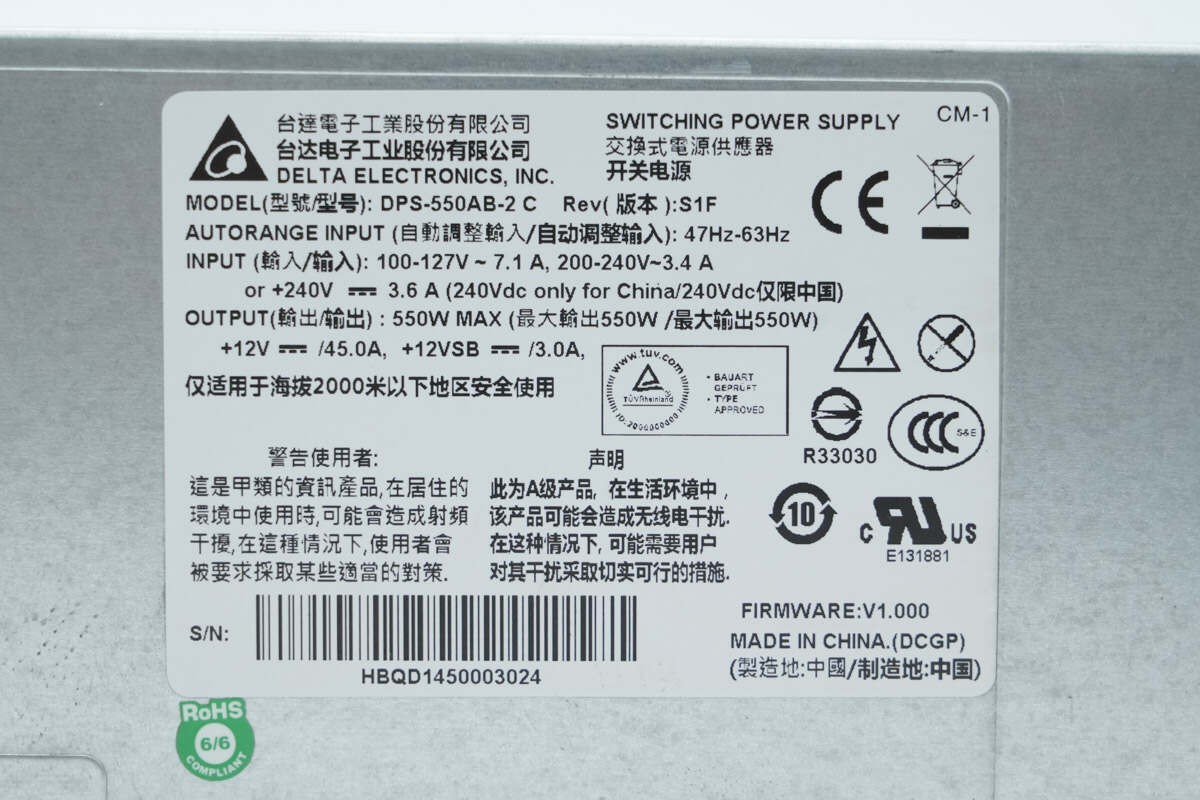
Model: DPS-550AB-2
Input: 100–127V ~ 7.1A,
200–240V ~ 3.4A
+240V ⎓ 3.6A (240V DC for use in China only)
Output: 550W MAX
+12V ⎓ /45A, +12VSB ⎓ /3A
Grounding spring contacts are also provided on the rear side.

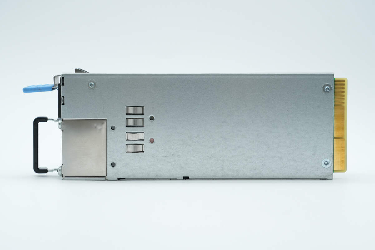
The side of the enclosure is secured with screws.

The input side features a cooling fan, handle, input socket, indicator light, and release latch.
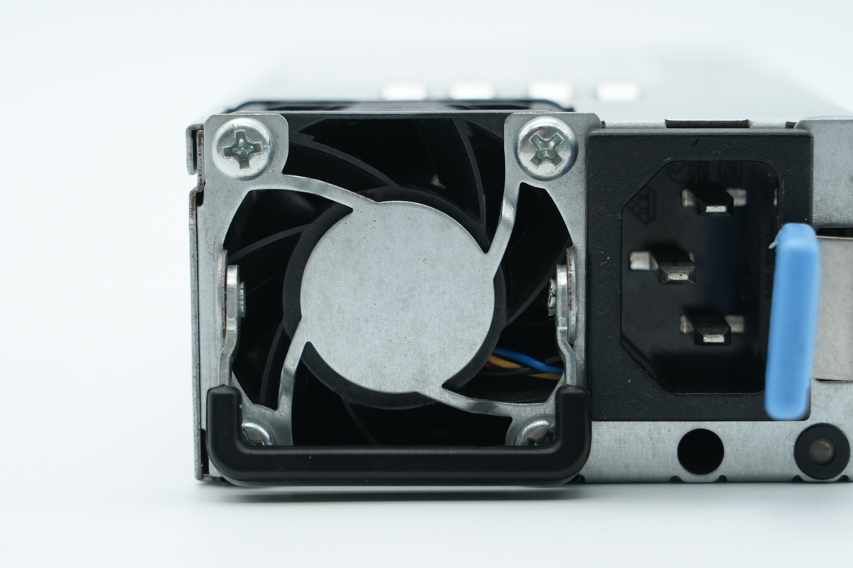
The cooling fan is equipped with a protective grill.

Close-up of the three-prong input socket.
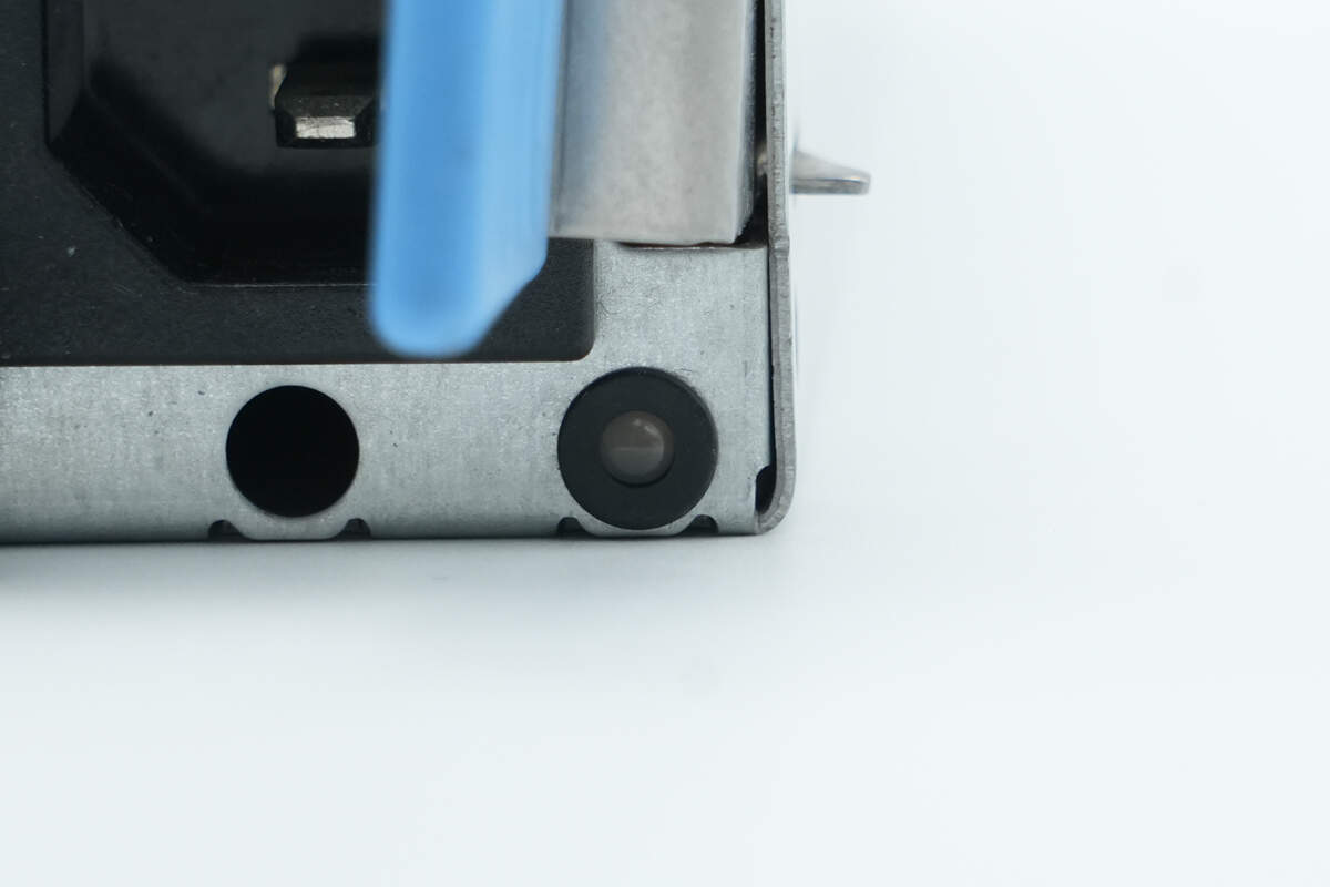
Below is the LED indicator.

The output side features a gold-finger connector and a ventilation grille.
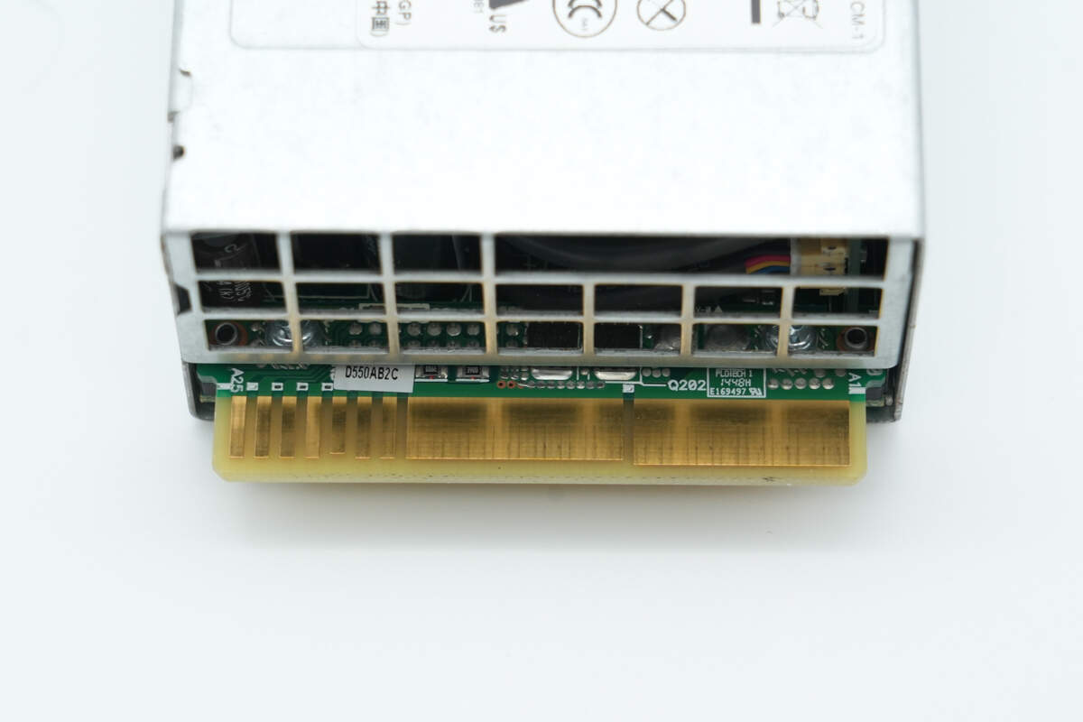
Close-up of the gold-finger connector.
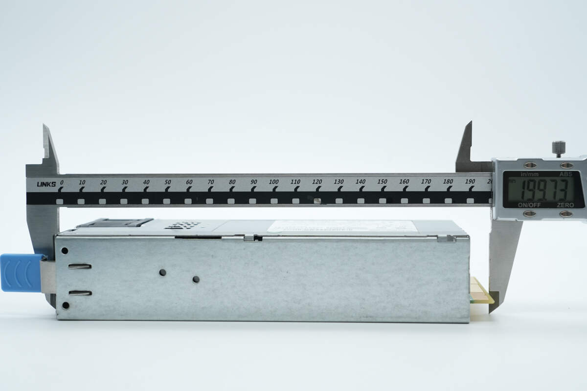
The length of the module is about 200 mm (7.87 inches).
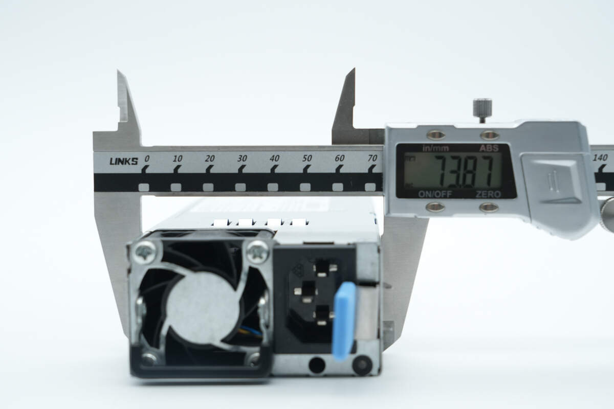
The width is about 73.9 mm (2.91 inches).
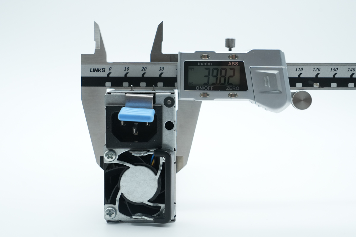
The thickness is about 39.8 mm (1.57 inches).
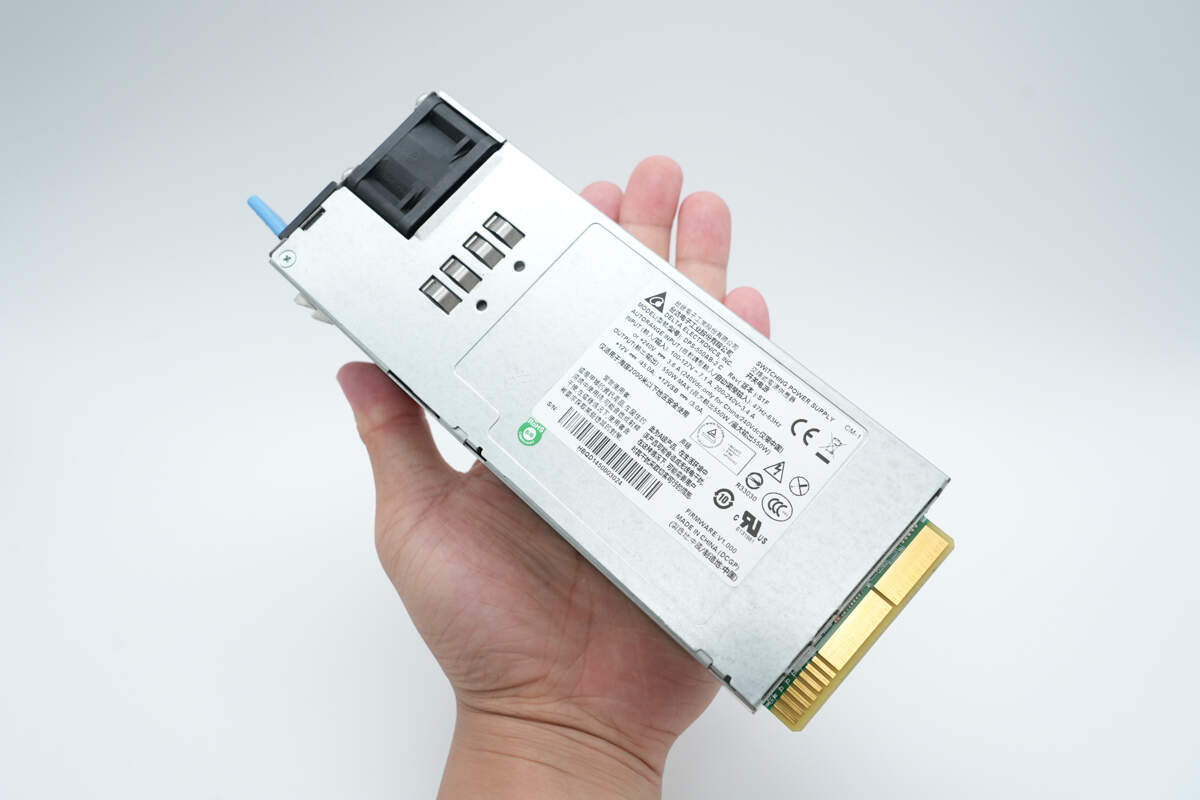
That's how big it is in the hand.
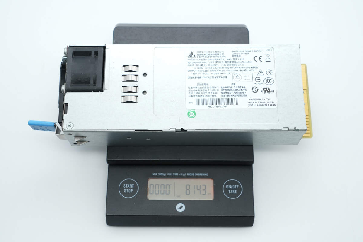
The weight is about 814.3 g (28.72 oz).
Teardown
Next, let's take it apart to see its internal components and structure.

Remove the enclosure. The PCBA module is covered with a transparent Mylar sheet.
The PCBA module is secured with screws.
The LED indicator and cooling fan are connected via connectors.
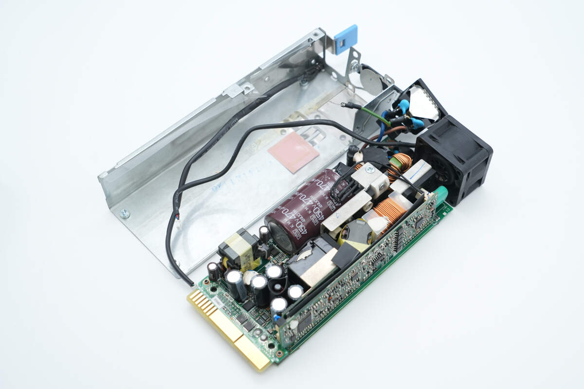
Remove the PCBA module.

Inside the housing, there is a transparent Mylar sheet. The sheet has openings corresponding to the PCB positions and is fitted with a thermal pad.
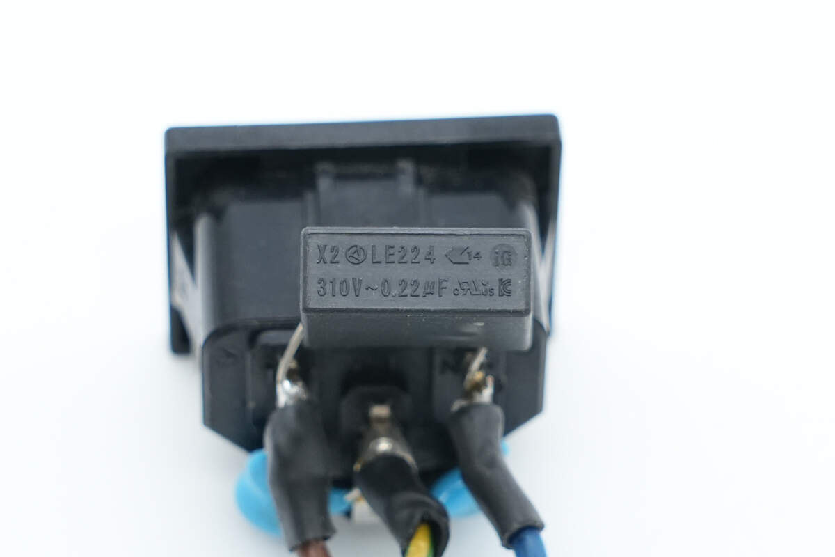
The safety X2 capacitor is from OKAYA, with a specification of 0.22 μF.
The blue Y capacitor is from MURATA.
The input wires are insulated with heat shrink tubing.
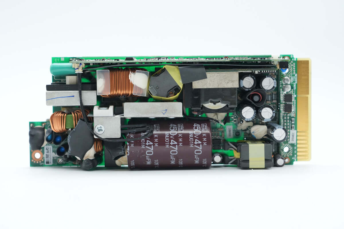
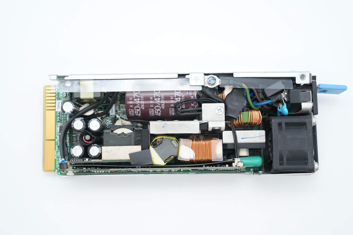
The front side of the PCBA module contains the following components: fuse, Y capacitors, varistor, common mode chokes, relay, thermistor, safety X2 capacitor, bridge rectifier, film capacitor, PFC boost inductor, resonant inductor, PFC MOSFET, LLC MOSFETs, high-voltage filter capacitor, transformer, filter capacitors, filter inductor, and auxiliary power transformer.

On the back side, foam is placed on both sides to prevent foreign objects from entering, and there is also a thermal pad.

The back side is equipped with a current-sensing resistor, LLC controller, standby power MOSFET, synchronous rectifier controller, synchronous rectifiers, and a voltage comparator.
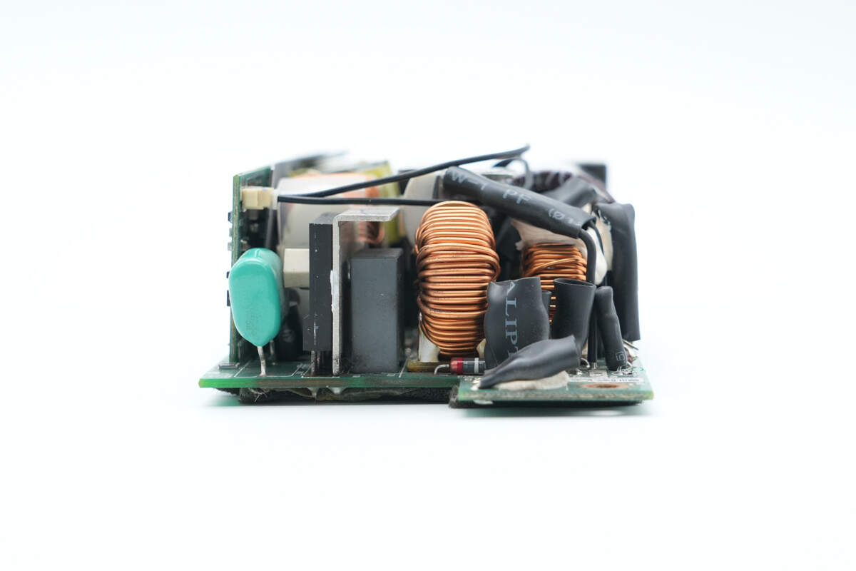
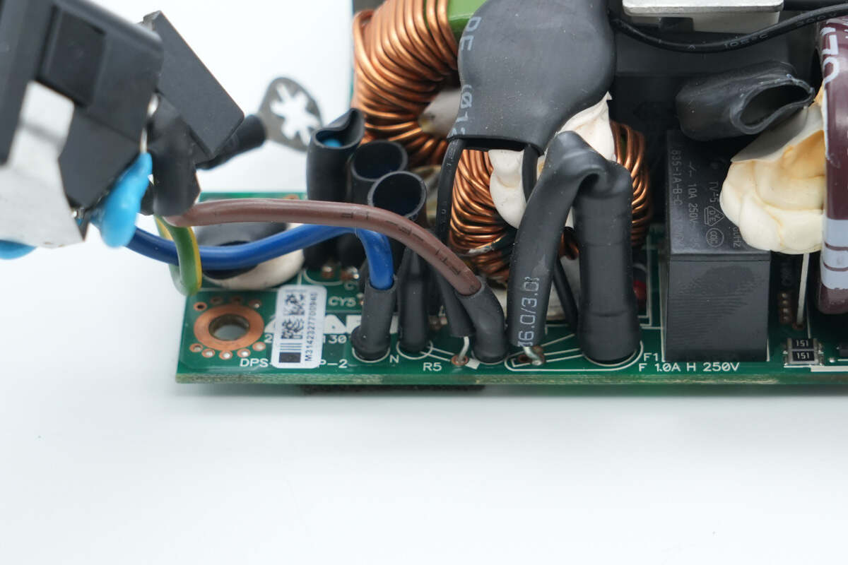
The input side is equipped with a fuse, varistor, common mode choke, safety X2 capacitor, bridge rectifier, and film capacitor.
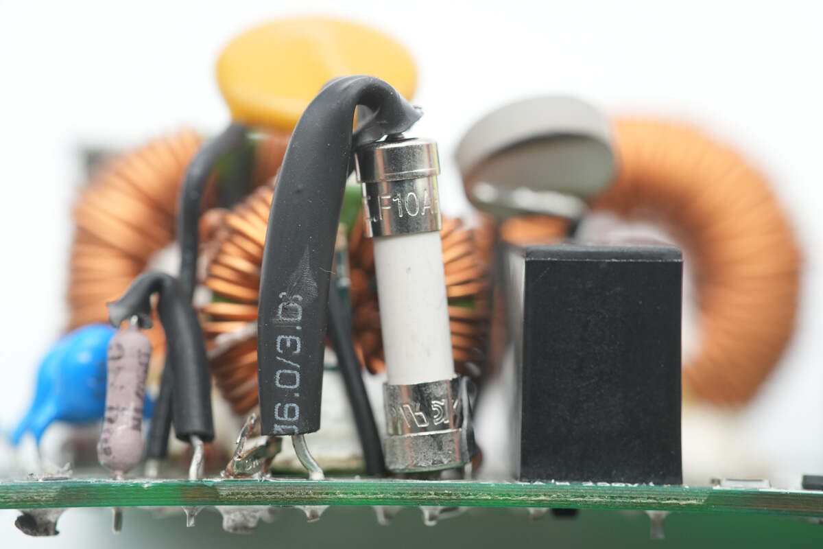
The input fuse has a rating of 10 A.
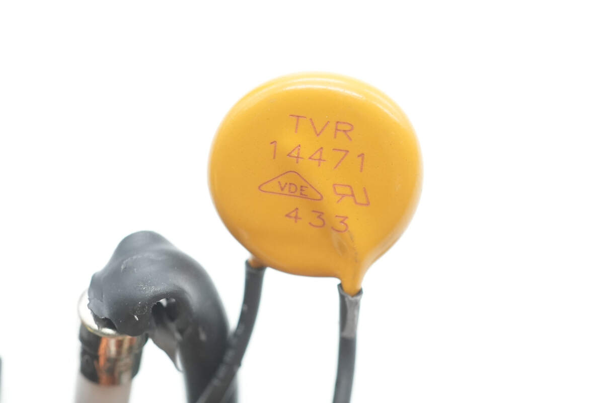
The varistor is model TVR14471 and is used to absorb overvoltage surges.
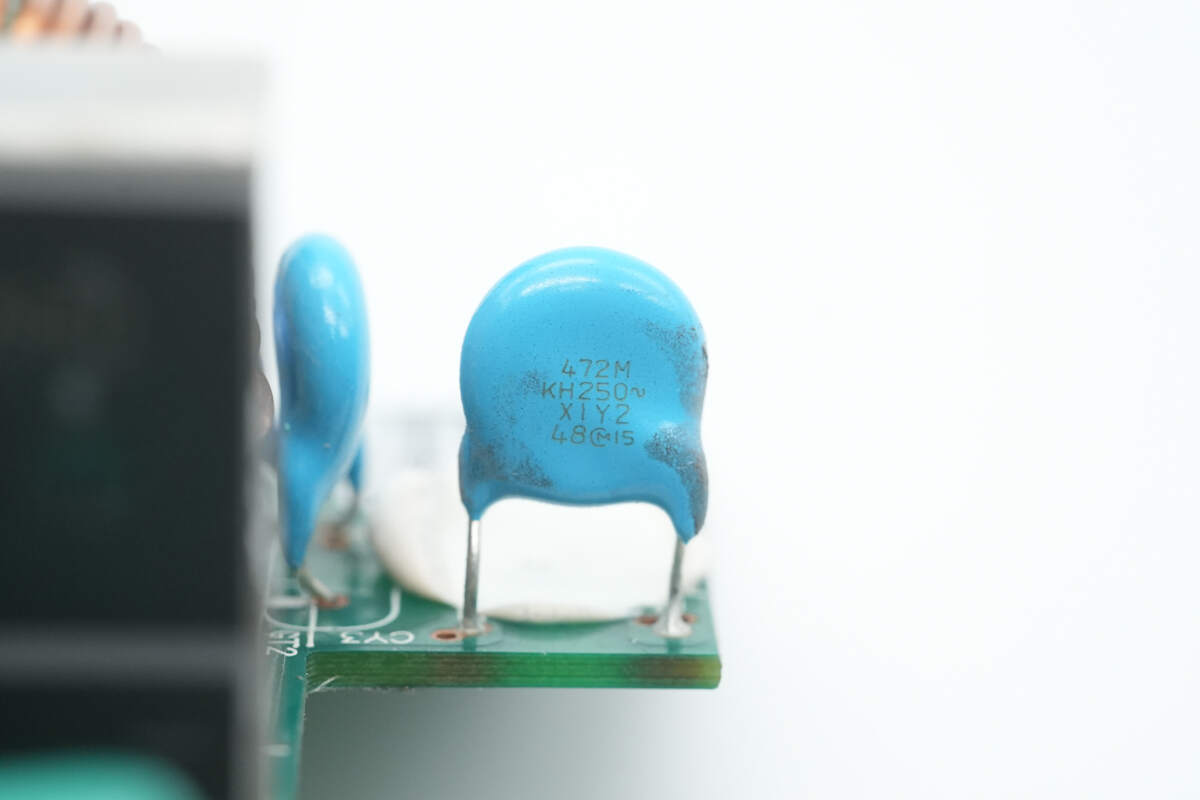
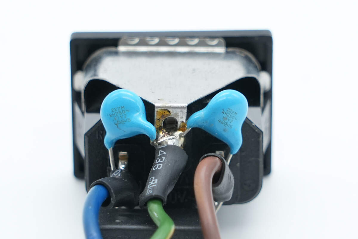
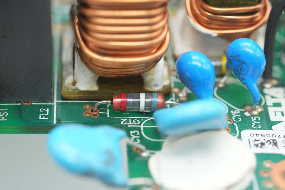
The blue Y capacitor is from MURATA.
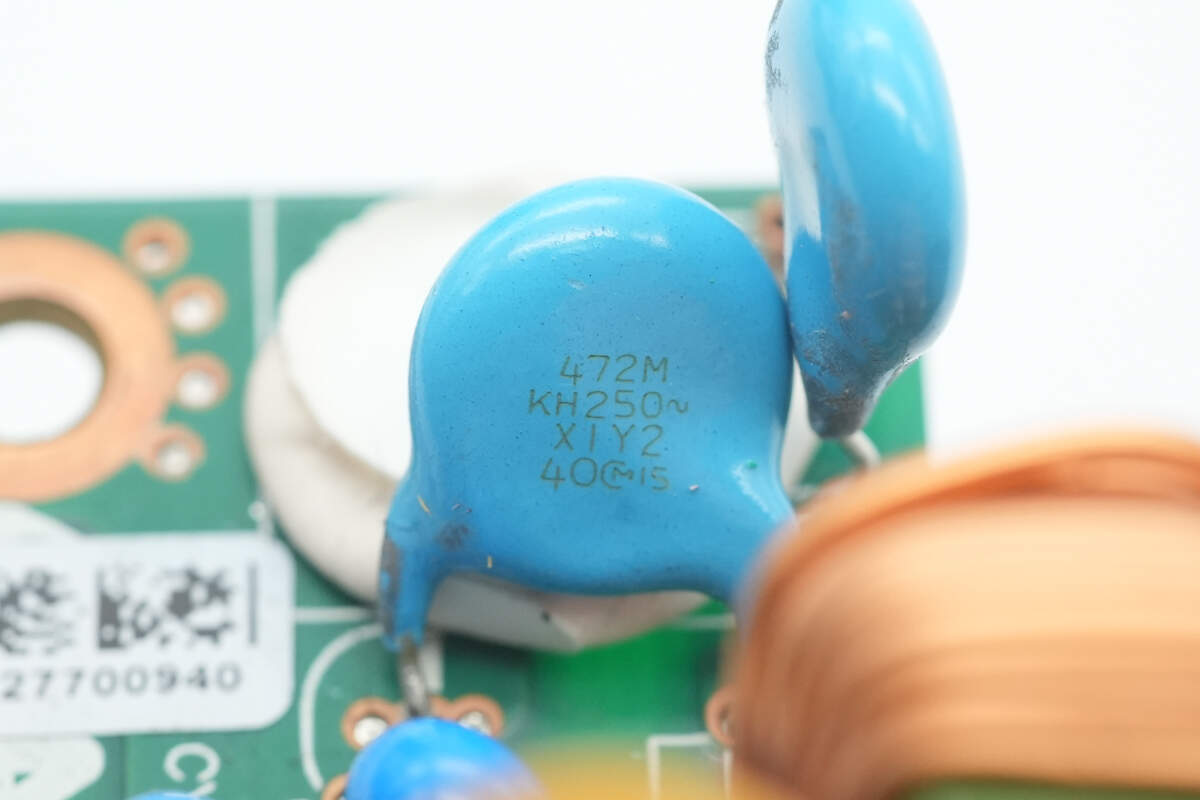
Another Y capacitor is also from MURATA.

Two Y capacitors are sourced from Walsin.
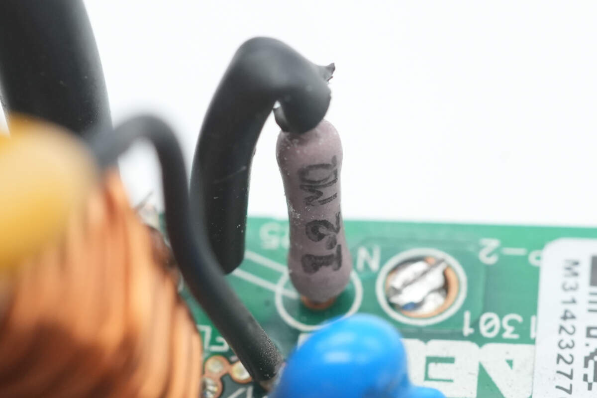
Close-up of the discharge resistor for the X capacitor.
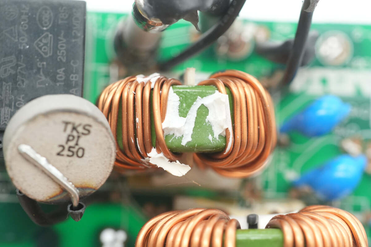
The common mode choke is wound with enameled wire.
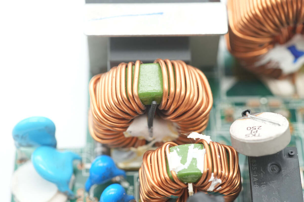
Another common mode choke is also wound with enameled wire.
Gas discharge tubes are installed on both sides of the common mode chokes.
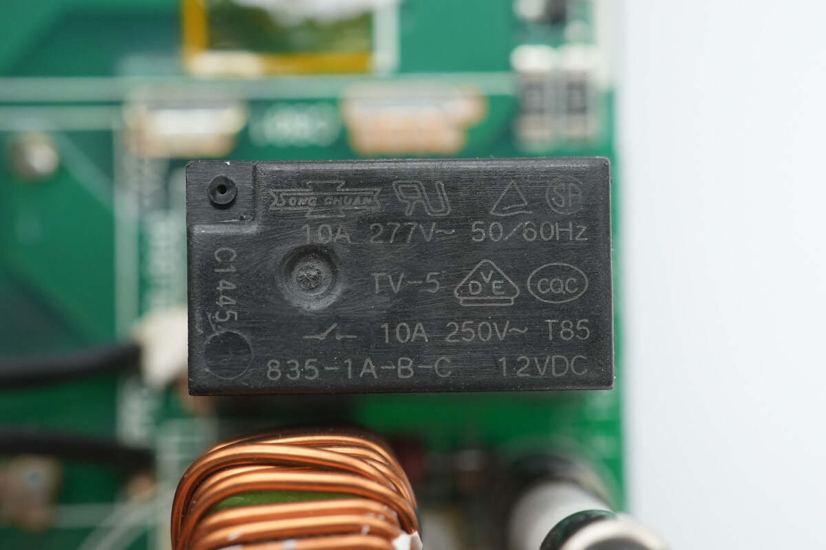
The relay is from SongChuan, model 835-1A-B-C, with a contact rating of 10 A 250 V and a coil voltage of 12 V, used for the short-circuit thermistor.
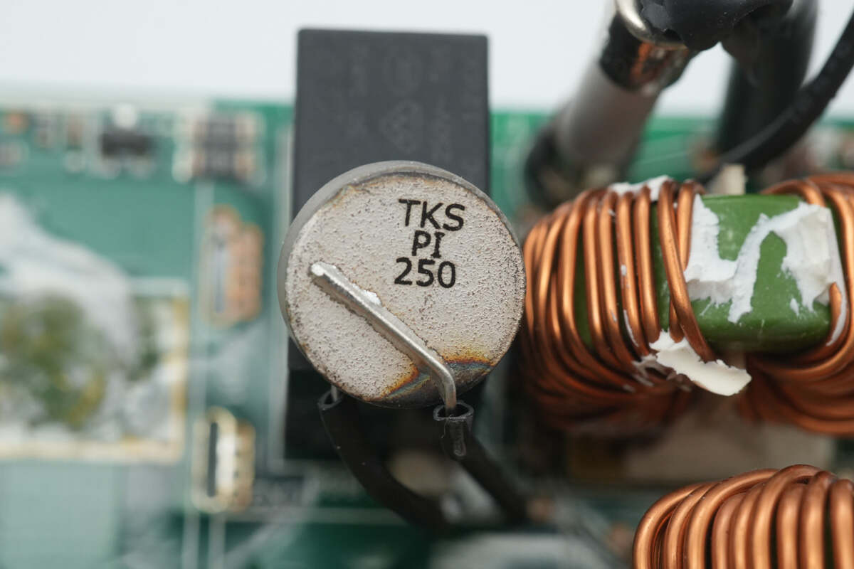
The thermistor is from Thinking, marked with PI 250.
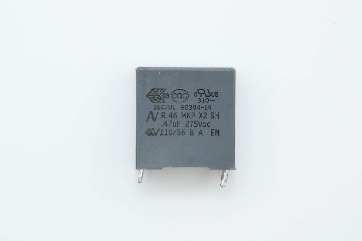
The safety X2 capacitor has a specification of 0.47 μF.
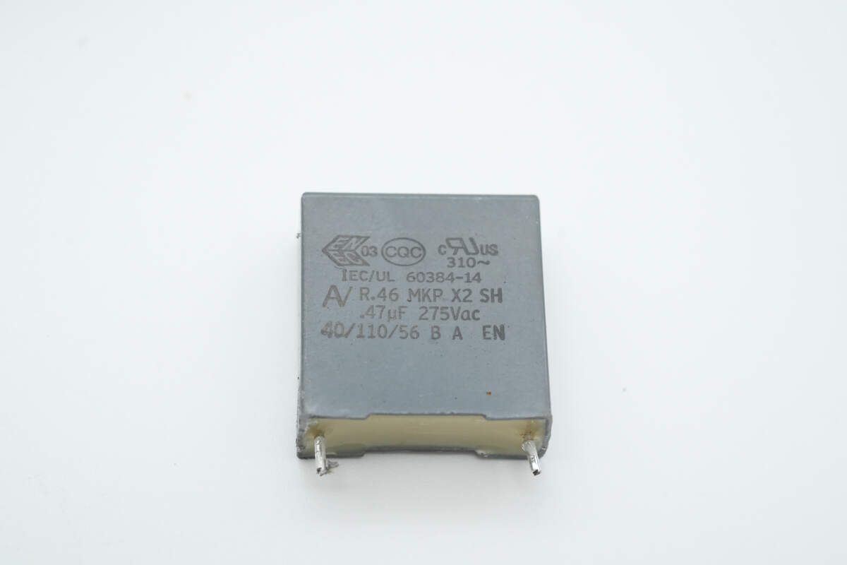
Another capacitor has the same specification of 0.47 μF.

The bridge rectifier is from Shindengen, model D25XB60, rated at 25 A 600 V, and comes in a 5S package.
The film capacitor is from SHINYEI, with a specification of 450 V, 1 μF.
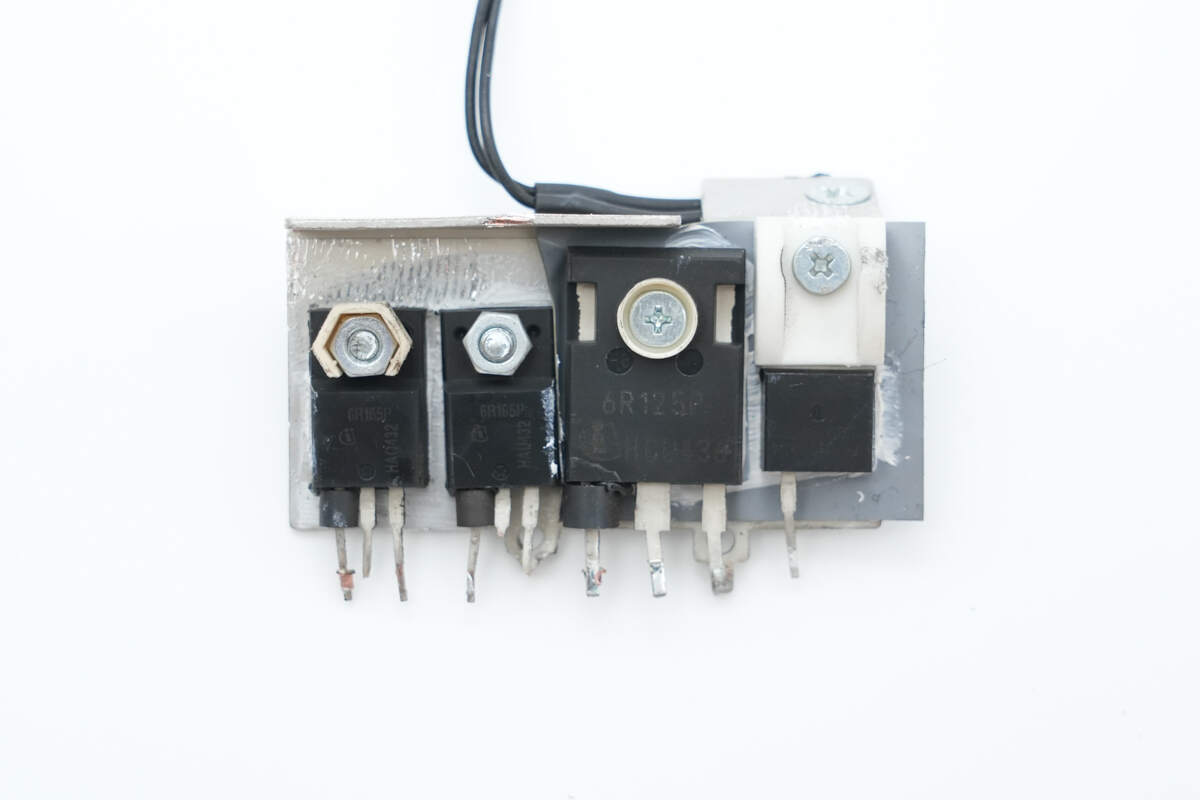
The front side of the heatsink is equipped with LLC MOSFETs, PFC MOSFET, and PFC rectifier.
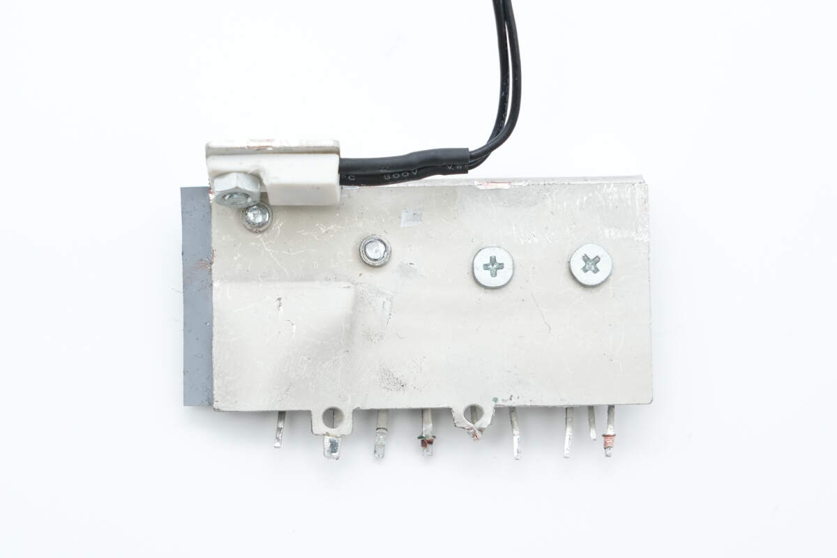
On the back side, there is a thermistor used for temperature rise detection.
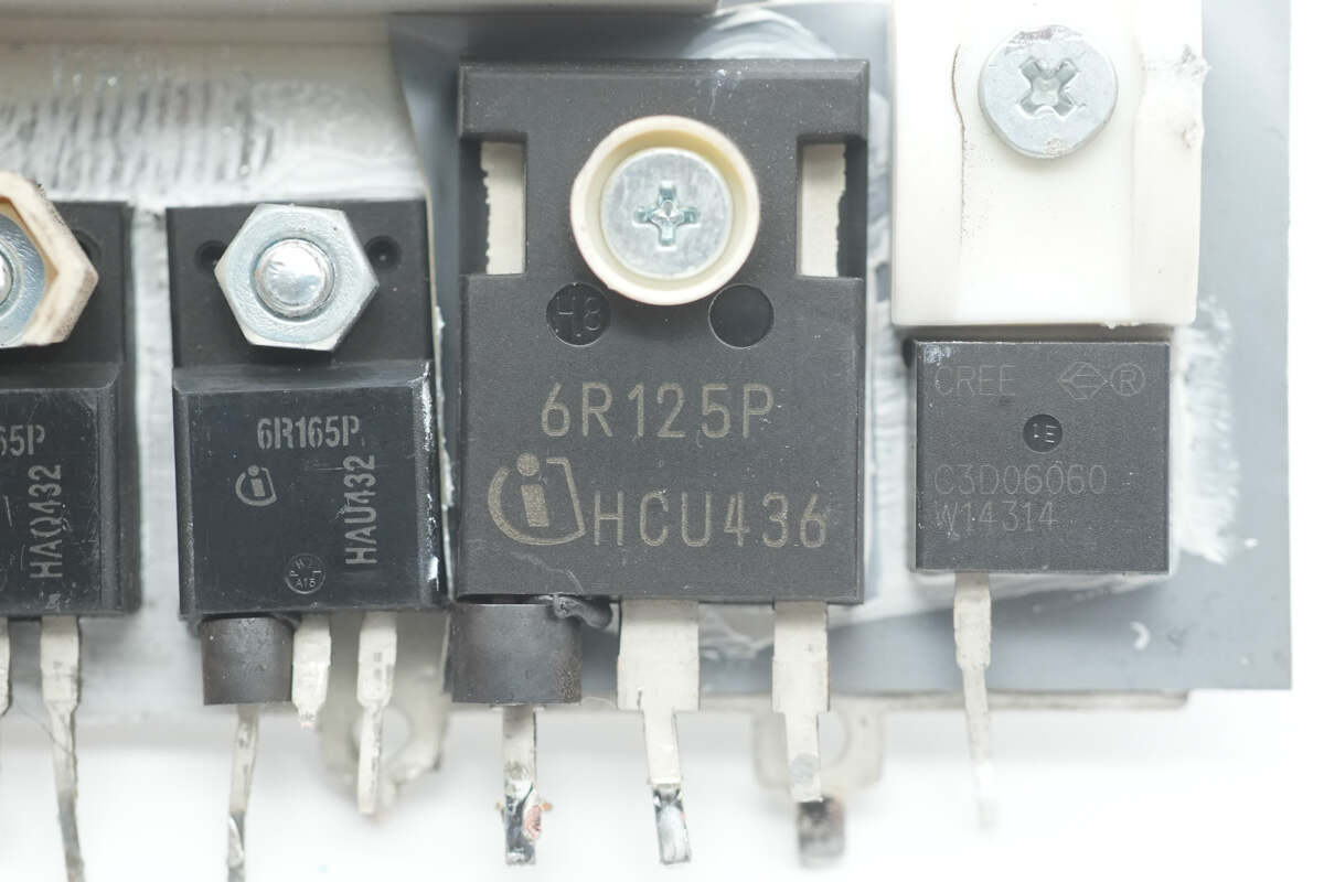
The PFC MOSFET is from Infineon, marked 6R125P, model IPW60R125CP. It is an NMOS with a voltage rating of 650 V, an on-resistance of 125 mΩ, and comes in a TO-247-3-1 package.
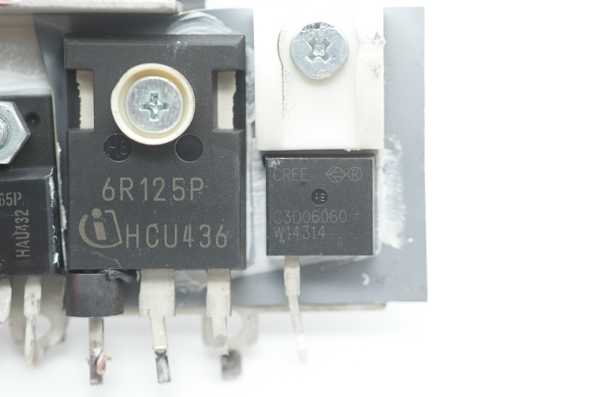
The PFC rectifier is from Wolfspeed, model C3D06060A. It is a silicon carbide (SiC) diode rated at 600 V, 6 A, and comes in a TO-220-2 package.
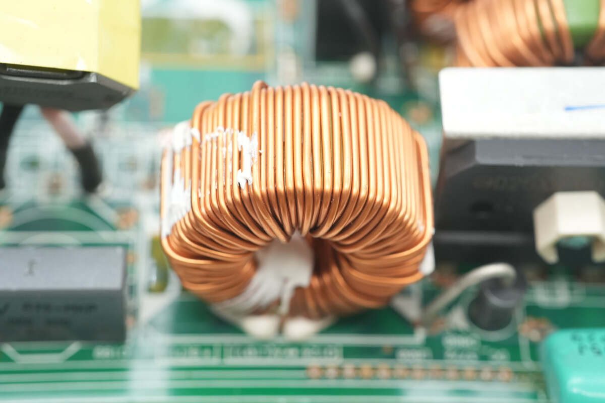
The PFC boost inductor is wound with enameled wire.
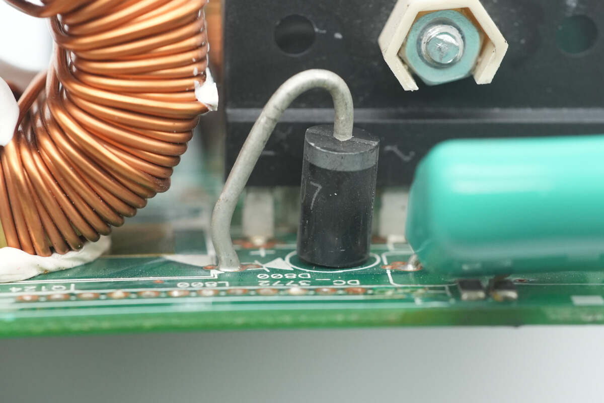
Close-up of the PFC bypass diode.
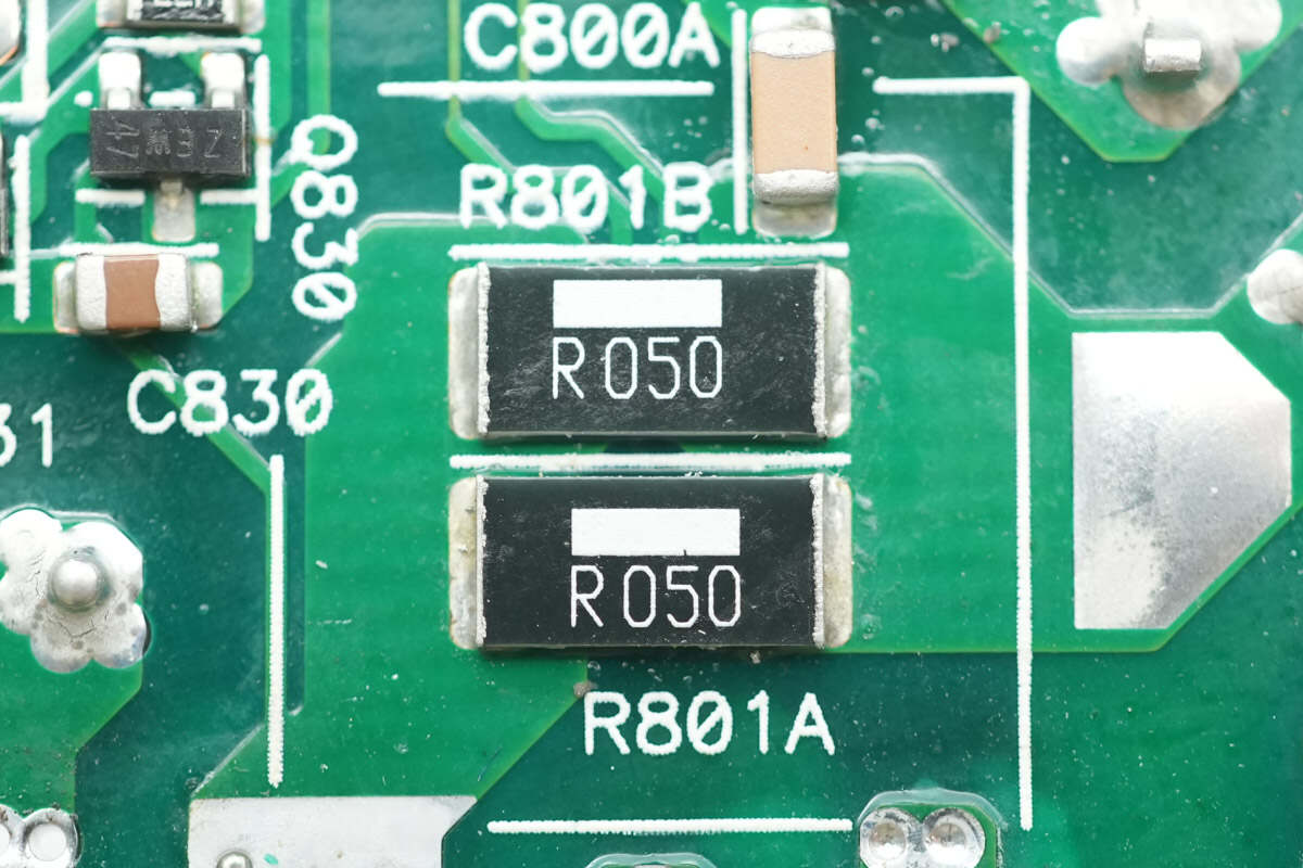
Two 50 mΩ resistors are connected in parallel to sense the current of the PFC MOSFET.

The high-voltage filter capacitor and standby power transformer are soldered on the side of the PCBA module.
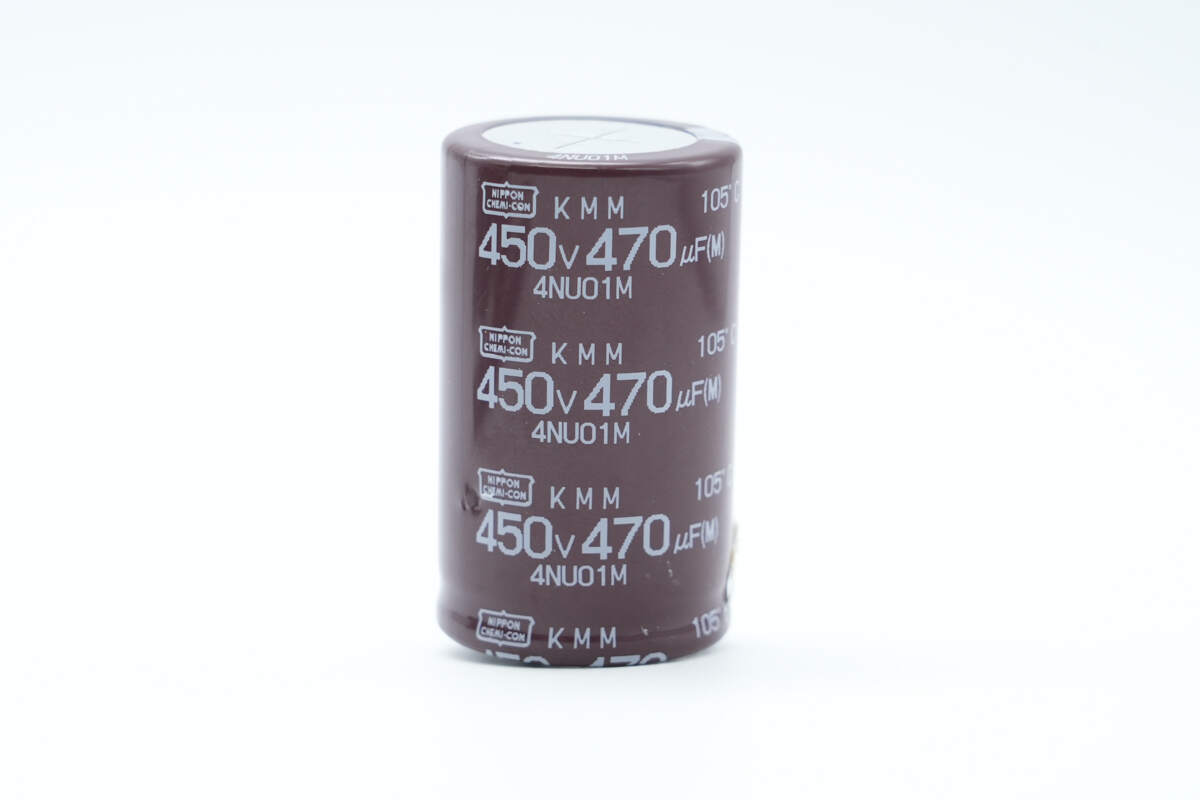
The high-voltage filter capacitor is from NCC, part of the KMM series of long-life electrolytic capacitors, with a specification of 450 V, 470 μF.
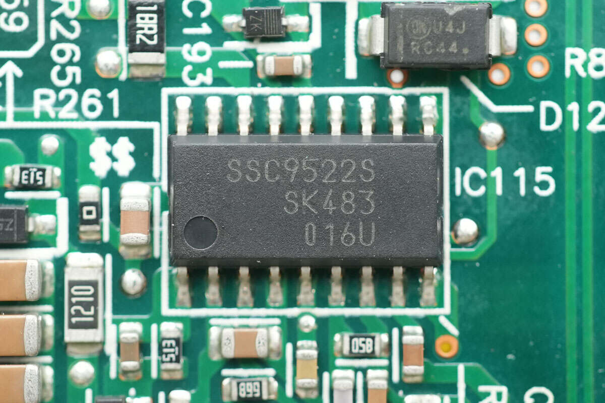
The LLC controller is from SanKen, model SSC9522S, designed for half-bridge resonant switching power supplies. It features a built-in floating gate driver for high-side MOSFETs, enabling high-efficiency, low-noise, and cost-effective power supply solutions with minimal external components. It comes in an SOP18 package.
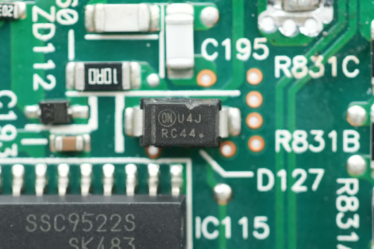
The ultra-fast recovery diode is from Onsemi, marked U4J, model MURA160, rated at 600 V, 1 A, and comes in an SMA package.
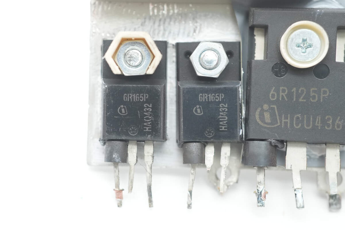
The LLC MOSFETs are from Infineon, marked 6R165P, model IPA60R165CP. They are NMOS with a voltage rating of 650 V, on-resistance of 165 mΩ, and come in a TO-220 package.
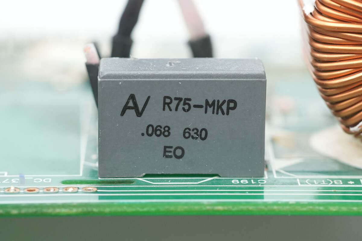
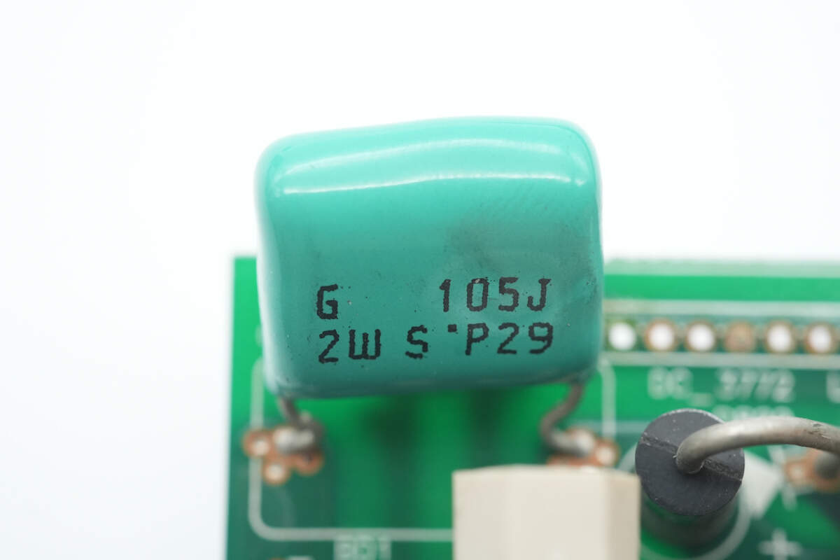
The resonant capacitor has a specification of 0.068 μF, 630 V.
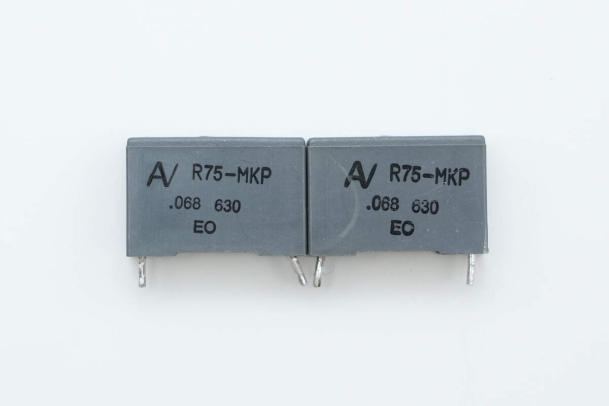
The other two resonant capacitors have the same specification of 0.068 μF, 630 V.
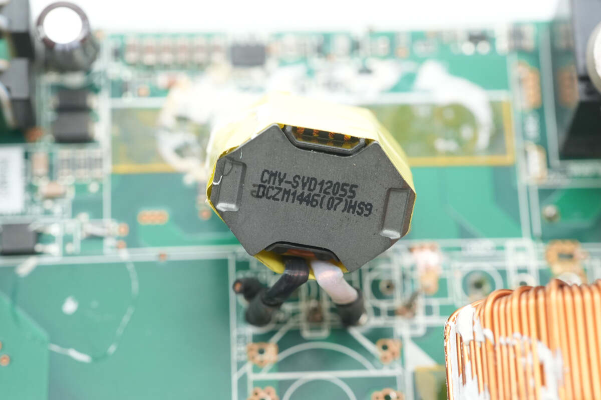
The resonant inductor is wound with Litz wire.
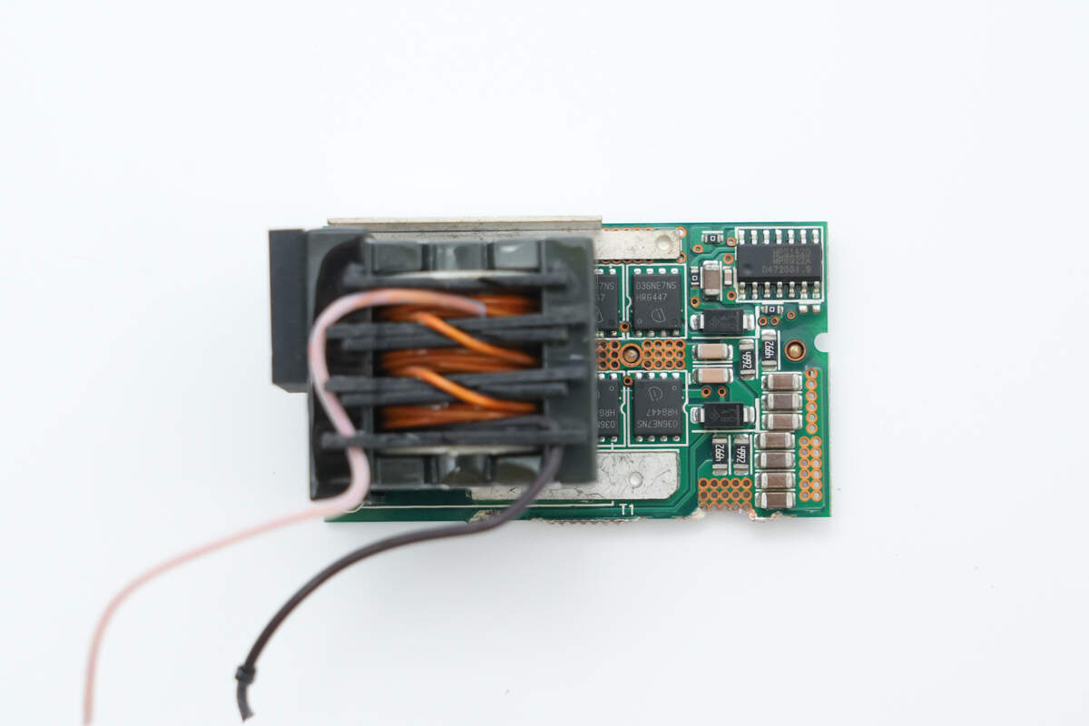
The synchronous rectifier PCB is equipped with a transformer, synchronous rectifier controller, and synchronous rectifiers.
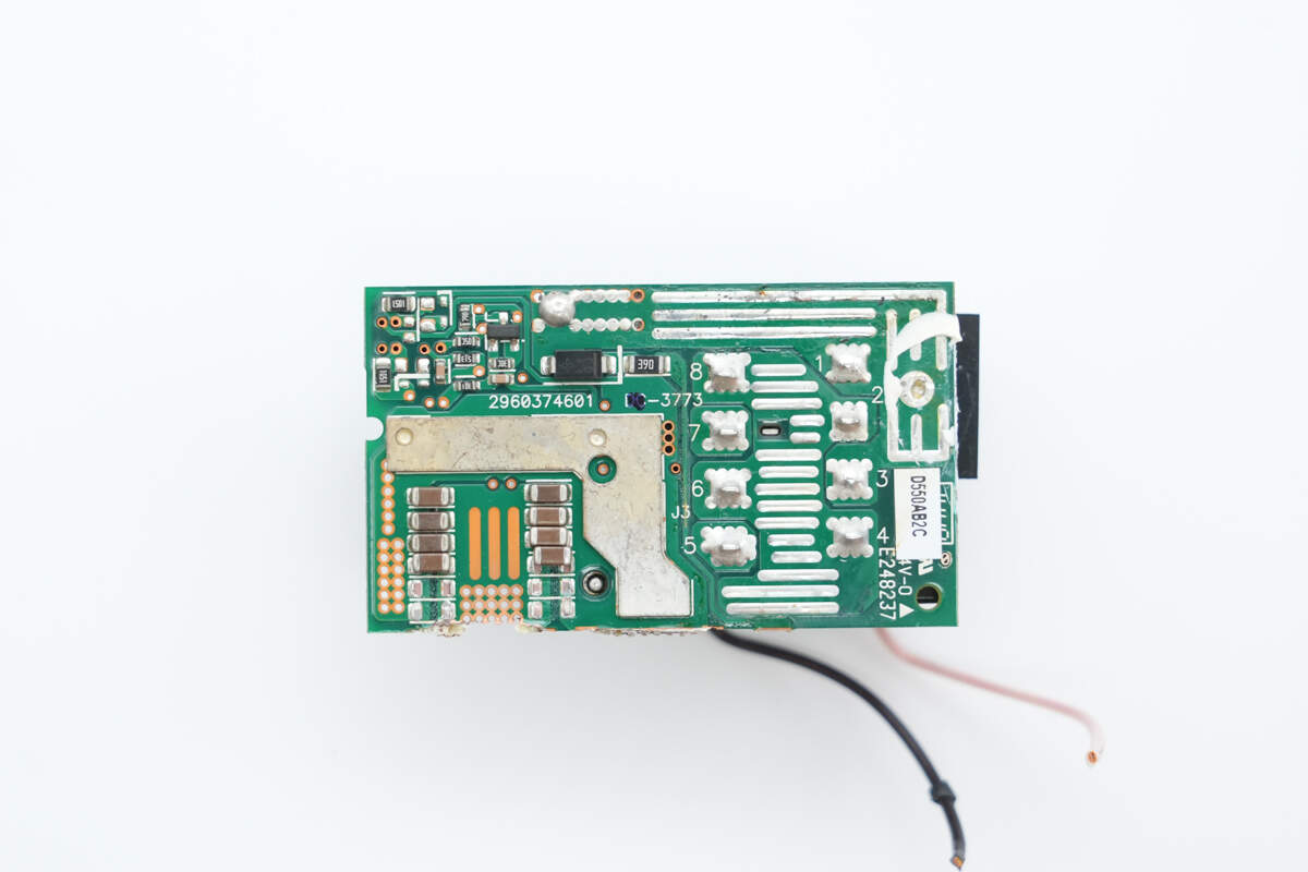
Copper bars are soldered on the back side to enhance current-carrying capacity.

The secondary of the transformer is soldered with copper strips.
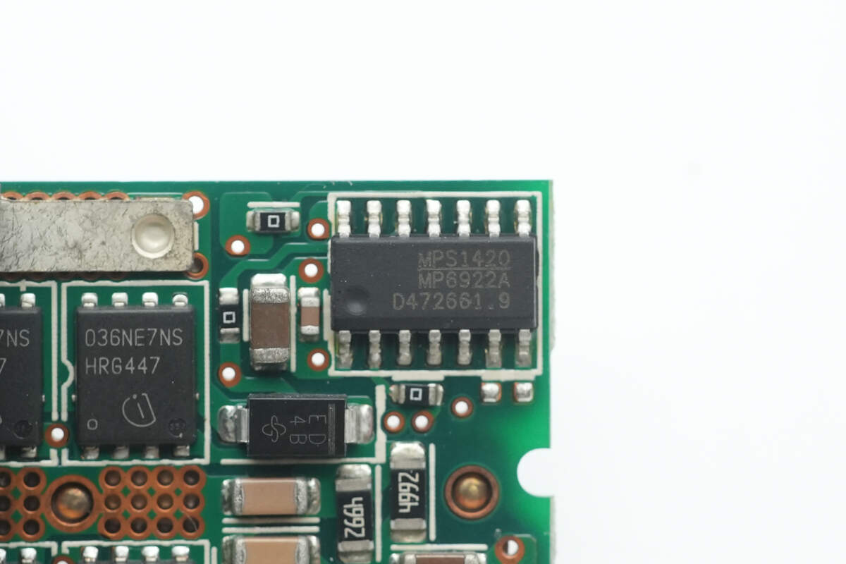
The synchronous rectifier controller is from MPS, model MP6922A, designed for LLC synchronous rectification. It supports CCM and DCM operating modes, standard and logic-level MOSFETs, an operating voltage range of 8–24 V, and light-load mode. It comes in an SOIC14 package.
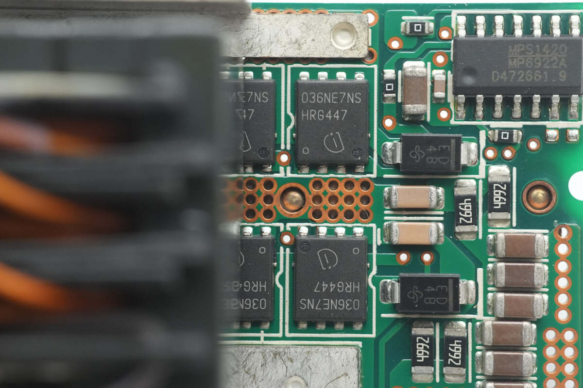
The synchronous rectifiers are from Infineon, model BSC036NE7NS3 G. They are NMOS with a voltage rating of 75 V, on-resistance of 3.6 mΩ, and come in a TDSON-8 package.
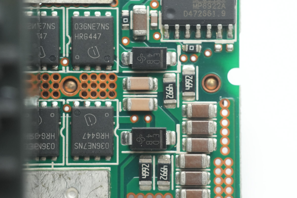
Two rectifier diodes are from VISHAY, marked ED, model ES1D, and come in an SMA package.
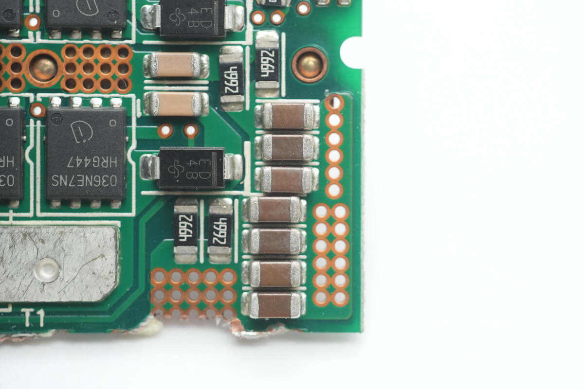
Close-up of the MLCC capacitors.
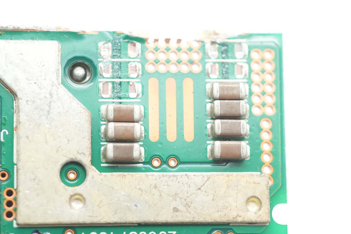
There are also MLCC capacitors on the back side.
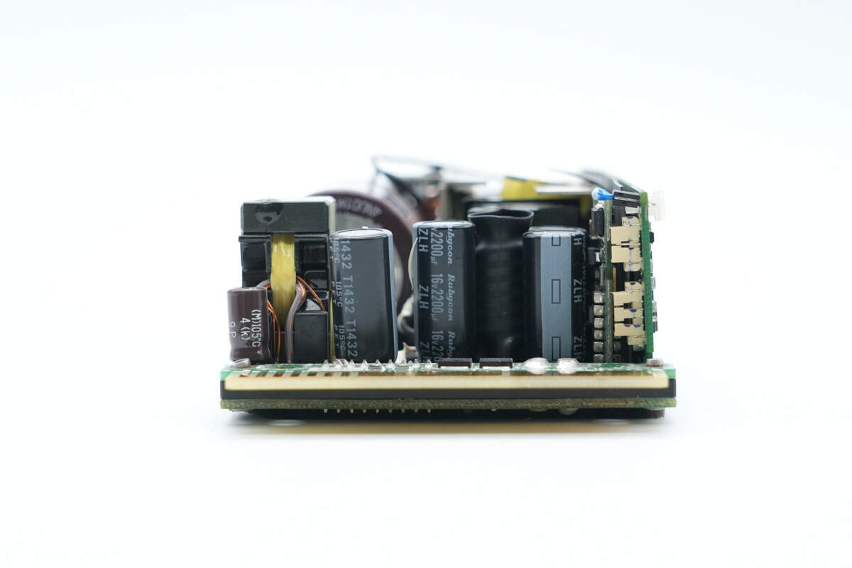
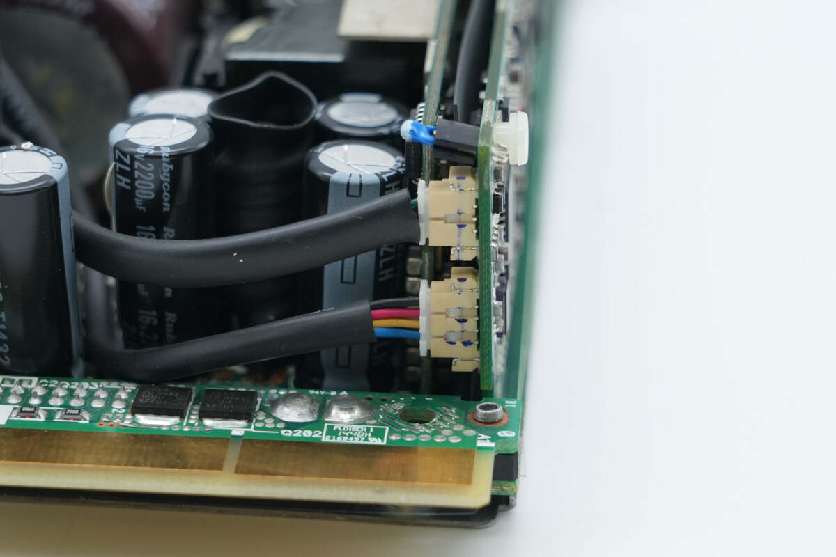
The output side is equipped with a standby power transformer, filter capacitors, and a filter inductor. The filter inductor is insulated with heat shrink tubing.
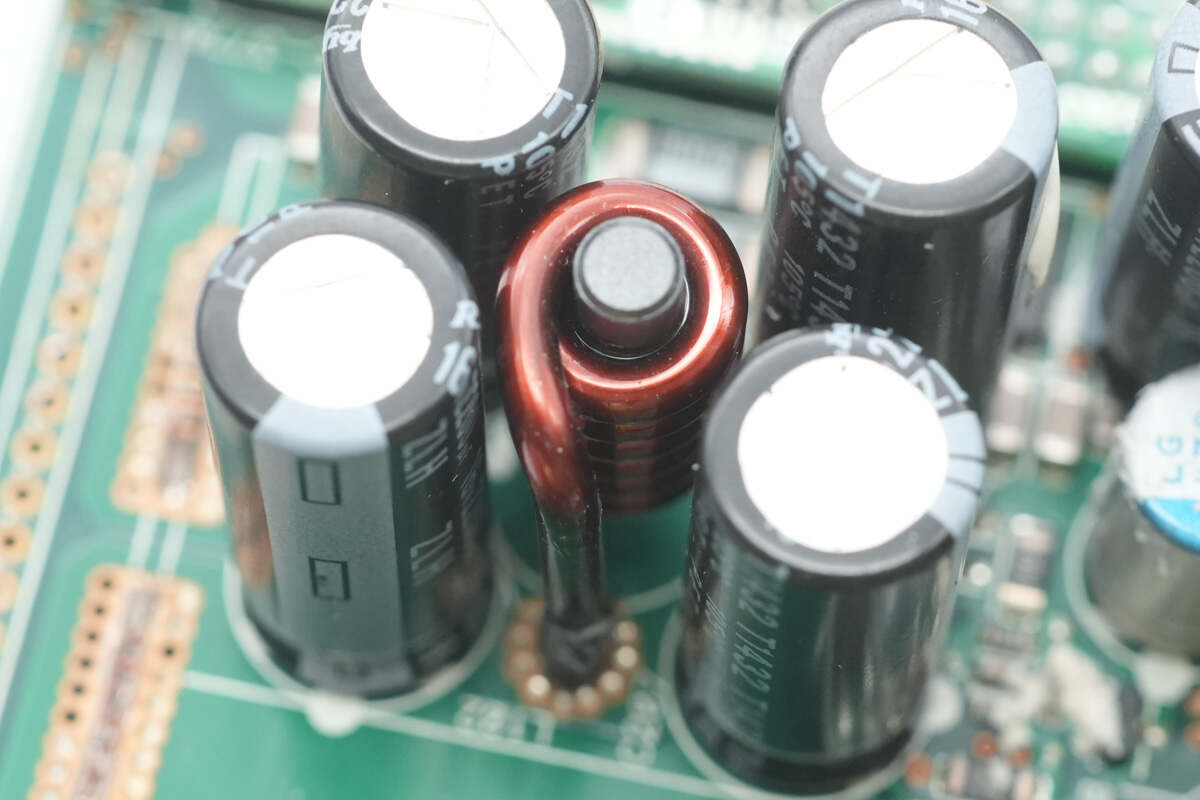
Four filter capacitors are arranged with a filter inductor in the middle.
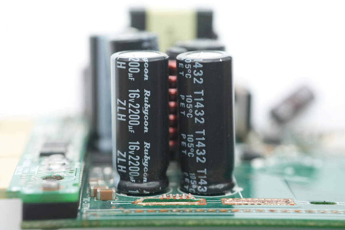
The filter capacitors are from Rubycon, each rated at 16 V, 2200 μF.